tier-4-gp2y0d413k / gpt-5.4-2026-03-05
1 run / 累計 14.0s / 累計 $0.0311
openai gpt 5.4 2026-03-05 pdf-page
bare (provider default effort)
run detail → render
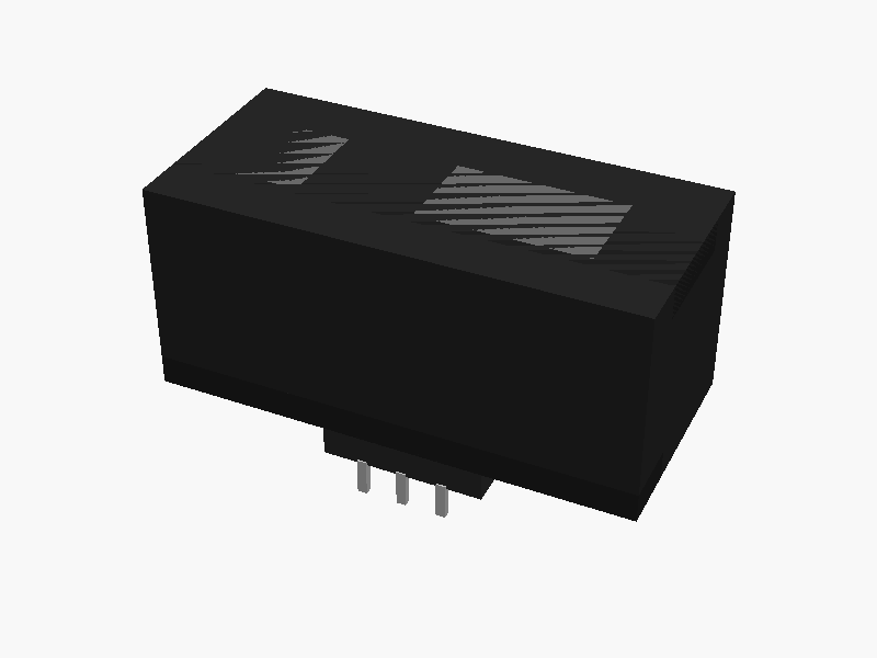
//
// Sharp GP2Y0D413K0F
// Simple mechanical model based on datasheet outline dimensions
//
// Coordinate system:
//   unit: mm
//   origin: center of main body
//   mounting face (PWB / connector side): toward -Z
//
// Notes:
// - This is a practical approximation of the exterior shape from the provided page.
// - Unspecified details are simplified.
// - Lens openings are represented as shallow recesses/reliefs on the front face.
//

$fn = 64;

// ==============================
// Parameters from datasheet
// ==============================

// Main body
body_w = 29.45;   // X
body_h = 13.5;    // Y
body_d = 13.05;   // Z

// Front face features
front_strip_h = 2.3;   // approximate top strip height visible in front view
bottom_skirt_h = 1.9;  // approximate lower strip height visible in front view

// Emitter / detector optical window layout (front view)
emit_center_x_from_left = 4.5;
det_center_x_from_left  = 19.7;
lens_center_y = 0;     // both centers lie on face mid-height in front view

emit_outer_w = 6.2;    // approximated square surround
emit_outer_h = 6.2;

emit_ring_od = 4.9;    // approximated from drawing
emit_ring_id = 3.3;

det_outer_w = 10.3;    // approximated detector lens frame
det_outer_h = 5.9;
det_ring_od = 4.7;
det_ring_id = 0.1;     // effectively filled center look

recess_depth = 0.8;    // shallow recess from front face

// Connector / PWB side
connector_w = 10.1;    // X
connector_h = 7.2;     // Y visible in front view
connector_d = 3.3;     // Z projection from mounting side (reference dim)

pwb_t = 1.2;           // board thickness
pwb_w = 8.0;           // simplified width inside connector
pwb_h = 6.0;           // simplified visible height

// Bottom connector details from bottom view
term_pitch = 2.54;
term_w = 0.6;
term_t = 0.5;
term_len = 2.3;

// Side-profile shoulder approximations
neck_d = 2.0;          // narrow section near front from side view
rear_step_d = 1.8;     // small step near rear / connector side

// Stamp on top
stamp_w = 8.0;
stamp_d = 3.2;
stamp_depth = 0.4;

// ==============================
// Helpers
// ==============================

function x_from_left(xl) = -body_w/2 + xl;

// Front is +Z, mounting/connector side is -Z
front_z =  body_d/2;
rear_z  = -body_d/2;

// ==============================
// Modules
// ==============================

module main_body() {
    difference() {
        cube([body_w, body_h, body_d], center=true);

        // top stamp recess
        translate([0, body_h/2 - 2.4, 1.5])
            rotate([90,0,0])
                linear_extrude(height=stamp_depth + 0.02)
                    offset(r=0.2)
                        square([stamp_w, stamp_d], center=true);
    }
}

module front_optics_detail() {
    // decorative / visible front lens structures, modeled as shallow raised/recessed frames
    // emitter side
    ex = x_from_left(emit_center_x_from_left);
    dx = x_from_left(det_center_x_from_left);

    // recessed rectangular areas
    color("dimgray")
    difference() {
        union() {
            // emitter square bezel
            translate([ex, 0, front_z - recess_depth/2])
                cube([emit_outer_w, emit_outer_h, recess_depth], center=true);

            // detector rectangular bezel
            translate([dx, 0, front_z - recess_depth/2])
                cube([det_outer_w, det_outer_h, recess_depth], center=true);
        }

        // emitter circular ring opening
        translate([ex, 0, front_z - recess_depth - 0.01])
            cylinder(h=recess_depth + 0.04, d=emit_ring_od, center=false);

        // detector circular opening
        translate([dx, 0, front_z - recess_depth - 0.01])
            cylinder(h=recess_depth + 0.04, d=det_ring_od, center=false);
    }

    // emitter ring lip
    color("black")
    translate([ex, 0, front_z - recess_depth/2])
    difference() {
        cylinder(h=recess_depth*0.9, d=emit_ring_od, center=true);
        cylinder(h=recess_depth*1.2, d=emit_ring_id, center=true);
    }

    // detector ring lip
    color("black")
    translate([dx, 0, front_z - recess_depth/2])
    difference() {
        cylinder(h=recess_depth*0.9, d=det_ring_od, center=true);
        if (det_ring_id > 0.2)
            cylinder(h=recess_depth*1.2, d=det_ring_id, center=true);
    }
}

module body_side_profile_accents() {
    // Simple side-profile approximation: front narrow nose and rear lower connector shoulder
    // Implemented as additive/subtractive bands across full width

    // front narrow nose band
    translate([0, 0, front_z - neck_d/2])
        cube([body_w, 7.2, neck_d], center=true);

    // rear small lower shelf toward connector side
    translate([0, -body_h/2 + 2.0, rear_z + rear_step_d/2])
        cube([body_w, 4.0, rear_step_d], center=true);
}

module connector_shell() {
    // connector protruding from mounting side (-Z)
    translate([0, -1.5, rear_z - connector_d/2])
        cube([connector_w, connector_h, connector_d], center=true);
}

module pwb_stub() {
    // visible board tongue inside connector area
    color([0.75, 0.65, 0.35])
    translate([0, -1.2, rear_z - pwb_t/2 - 0.2])
        cube([pwb_w, pwb_h, pwb_t], center=true);
}

module terminals() {
    color("silver")
    for (i = [-1,0,1]) {
        translate([i*term_pitch, -body_h/2 + 1.8, rear_z - connector_d - term_len/2 + 0.2])
            cube([term_w, term_t, term_len], center=true);
    }
}

module gp2y0d413k0f() {
    union() {
        color([0.15,0.15,0.15]) main_body();
        color([0.12,0.12,0.12]) body_side_profile_accents();
        color([0.18,0.18,0.18]) connector_shell();
        pwb_stub();
        terminals();
        front_optics_detail();
    }
}

// ==============================
// Render
// ==============================

gp2y0d413k0f(); パラメータ (32) —
スライダを動かすと openscad-wasm で再レンダリング
prompt
添付画像は Sharp 製距離センサ GP2Y0D413K0F のデータシートのページです。
OpenSCAD でモデリングしてください。

座標系: 単位 mm、本体の中心を原点とし、取付面(PWB / コネクタ側)を -Z に向ける。

完成したコード全体を ```openscad ... ``` のフェンスで囲んで出力してください。