vibe-openscad

tier-4-gp2y0d413k / google/gemma-4-e2b

1 run / 累計 17.9s / 累計 $0

google (self-hosted) gemma-4-e2b pdf-page

bare (provider default effort)

run detail →
render
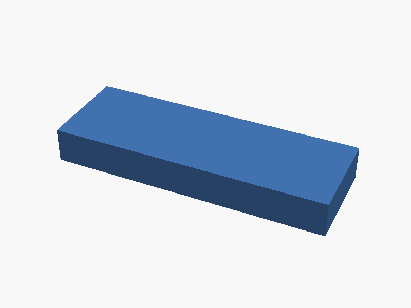
bare render of tier-4-gp2y0d413k
loading STL…
success 17.9s · 610/1715t
SCAD (79 lines)
// Sharp GP2Y0D413K0F Distance Sensor Outline Model
// Coordinate System: Center of body is (0, 0, 0). +Z is up. +Y is front. Units are mm.

// --- Dimensions based on the provided datasheet outline ---

// Main Body Case Dimensions (Approximate bounding box based on diagram)
main_width = 17.5;         // Total width/length approximation
main_height = 4.15;        // Height approximation
main_depth = 3.8;          // Depth approximation

// Front Protrusion / Lens Case Dimensions (relative to the main body)
protrusion_width = 6.3;    // Width of the front protrusion
protrusion_length = 7.1;   // Length/depth of the front part

// Lens Placement and Size (Based on the diagram's internal structure)
lens_center_x = 0;         // Center alignment assumed at X=0 for simplicity
lens_center_y = protrusion_length / 2 + main_height / 2; // Y position of the front face

// Lens/Window dimensions (approximated based on typical layout and provided reference)
light_lens_radius = 3.1;   // Approximate radius for one lens
receive_lens_width = 4.15; // Approximate width for the receiver area

// PWB Dimensions (Underneath attachment)
pwb_width = main_width;
pwb_depth = main_depth - 0.1; // Allowing minimal space for mounting

// Connector Footprint (3-pin JCTC connection approximation)
connector_size_x = 5;
connector_size_y = 2;


// --- Modeling the Sensor ---

module sharp_sensor() {
    // 1. 本体ケース (Main Body Case - Carbonic ABS, Rectangular block centered at origin)
    color("gray") {
        cube([main_width, main_height, main_depth], center = true);
    }

    // 2. 前面に飛び出すレンズケース (Front Lens Case / Protrusion)
    // This part protrudes forward (+Y direction) and slightly upward/downward depending on exact geometry.
    translate([0, 0, -main_depth / 2]) {
        color("gray") {
            cube([protrusion_width, main_height, protrusion_length], center = true);
        }
    }

    // 3. 発光部レンズ (Light Lens - Circular Window)
    // Positioned on the front face of the protrusion.
    translate([protrusion_width / 2, main_height / 2, -main_depth / 2]) {
        color("cyan") { // Light source approximation
            cylinder(r = light_lens_radius, h = 1, center = true);
        }
    }

    // 4. 受光部レンズ (Receive Lens - Rectangular Window)
    // Positioned on the front face of the protrusion.
    translate([protrusion_width / 2 + light_lens_radius, main_height / 2, -main_depth / 2]) {
        color("yellow") { // Receive area approximation (rectangle)
            cube([receive_lens_width, light_lens_radius * 2, 1], center = true);
        }
    }

    // 5. 下部に取り付けられる PWB (Printed Circuit Board - Thin plate underneath)
    translate([0, 0, -main_depth / 2]) {
        color("darkblue") {
            cube([pwb_width, pwb_depth + 0.1, 1], center = true); // Slightly thicker than the case
        }
    }

    // 6. 底面の 3 ピンコネクタ (3-Pin Connector - Simplified footprint)
    translate([main_width / 2 - connector_size_x/2, main_height / 2 + 1.5, -main_depth / 2 - 0.5]) {
        color("red") {
            cube([connector_size_x, connector_size_y, 1], center = true);
        }
    }
}

sharp_sensor();
パラメータ (10)
スライダを動かすと openscad-wasm で再レンダリング

prompt

添付の Sharp 製距離センサ GP2Y0D413K0F のデータシート 2 ページ目には、
本体の外形寸法図(Outline Dimensions)が描かれています。図を読み取り、
OpenSCAD でセンサの外形をモデリングしてください。

含めるべき部位:
- 本体ケース(Carbonic ABS、概形は直方体)
- 前面に飛び出すレンズケース(2 つの窓を持つ突起)
- 発光部レンズ(円形の窓、左側)と受光部レンズ(矩形の窓、右側)
- 下部に取り付けられる PWB(プリント基板、薄板)
- 底面の 3 ピンコネクタ(JCTC 12001W90-3P-HF、簡易表現で可)

寸法:
- 図中のミリメートル数値に従ってください
- "*" 印が付いた寸法はレンズ中心位置を示す参照寸法です
- 括弧 `( )` で囲まれた値は参考寸法
- "Unspecified tolerances shall be ± 0.3 mm" に従ってよい

座標系:
- 本体の中心が原点。+Z は上方向(コネクタが下、レンズが前面 +Y)
- 単位は mm

内部の IC や回路素子はモデリング不要、外形だけで十分です。
完成したコード全体を ```openscad ... ``` のフェンスで囲んで出力してください。
コードのみで、追加の説明は不要です。