tier-4-gp2y0d413k / claude-sonnet-4-6
1 run / 累計 48.3s / 累計 $0.0463
claude sonnet 4.6 pdf-page
bare (provider default effort)
run detail → render
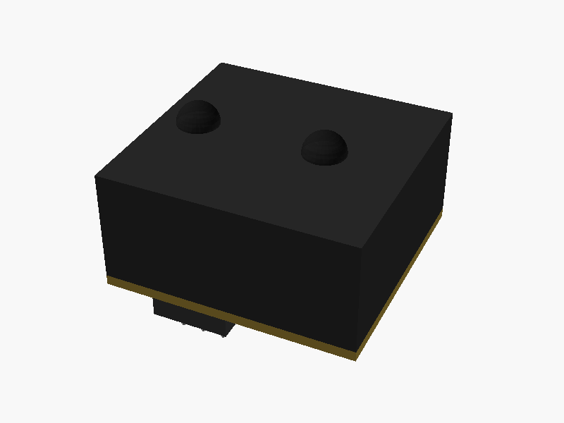
// Sharp GP2Y0D413K0F Distance Sensor
// Unit: mm
// Origin: center of main body
// -Z: mounting face (PWB/connector side)

// -------------------------------------------------------
// Key dimensions from datasheet
// -------------------------------------------------------
// Overall body (main case)
body_w   = 29.45;  // X width (left-right in front view)
body_d   = 13.5;   // Y depth (front-back, from bottom view: 7.5+4.15+16.3 total=28 but case is ~13.5)
body_h   = 13.05;  // Z height of main body (top of lens case reference)

// Re-reading: bottom view shows depth 7.5+4.15+16.3 = 27.95 ≈ 28mm total board depth
// Side view shows body height 8.4mm (case), with total 13.05 to top of lens
// Let's use:
//   board depth (Y): 28mm
//   main case height (Z, above PWB): 8.4mm
//   lens protrusion above case: 13.05 - 8.4 = 4.65mm (lens case)
//   PWB thickness: 1.2mm
//   connector below PWB: 3.3mm (reference)

total_depth  = 28.0;    // Y total (board)
case_h       = 8.4;     // main case height above PWB top surface
pwb_t        = 1.2;     // PWB thickness
conn_h       = 3.3;     // connector protrusion below PWB (reference)
lens_case_h  = 13.05;   // top of lens case from top of PWB (= case_h + lens dome portion)

// total Z height = pwb_t + case_h + (lens_case_h - case_h) = pwb_t + lens_case_h
total_h = pwb_t + lens_case_h; // = 1.2 + 13.05 = 14.25mm

// Origin: center of body, -Z = bottom of PWB (mounting face)
// So Z=0 is at center of total height
// Z range: -total_h/2 to +total_h/2  but mounting face at -Z
// Let's place: PWB bottom at z = -total_h/2
// PWB top    at z = -total_h/2 + pwb_t
// Case top   at z = -total_h/2 + pwb_t + case_h
// Lens top   at z = +total_h/2

z_bottom = -total_h / 2;   // PWB bottom (mounting face)
z_pwb_top = z_bottom + pwb_t;
z_case_top = z_pwb_top + case_h;
z_lens_top = z_pwb_top + lens_case_h; // = total_h/2

// Lens positions (from left edge, X direction)
// Left edge of body at x = -body_w/2
lens_emitter_x = -body_w/2 + 4.5;   // *4.5 from left
lens_detector_x = -body_w/2 + 19.7; // *19.7 from left

// Lens diameters (estimated from drawing, ~5mm each)
lens_r = 2.5;
lens_dome_h = lens_case_h - case_h; // protrusion above case = 4.65mm

// Lens case width (the raised portion for lenses)
// From drawing: lens case is 7.1mm wide centered around lenses, 6.3mm inset
lens_case_w = 7.1;  // width of lens case protrusion
lens_case_x_center = (lens_emitter_x + lens_detector_x) / 2;

// Side connector tab dimensions (side view shows stepped bottom)
// Inner step: 10.1mm wide, 3.75mm high from bottom of body
step_w = 10.1;
step_h = 3.75; // step height from bottom of main body face

// bottom view connector area: centered at x around connector region
// Connector (bottom view): 7.5 from left edge, 4.15 wide
conn_x_offset = -body_w/2 + 7.5 + 4.15/2;
conn_w = 4.15;
conn_d = 8.0; // approx connector depth

// Colors
case_color   = [0.15, 0.15, 0.15, 1.0]; // dark ABS
pwb_color    = [0.6,  0.5,  0.2,  1.0]; // paper phenol (yellowish)
lens_color   = [0.1,  0.1,  0.1,  0.7]; // dark lens (IR cut)
conn_color   = [0.8,  0.8,  0.8,  1.0]; // connector pins

// -------------------------------------------------------
// Modules
// -------------------------------------------------------

module pwb() {
    color(pwb_color)
    translate([0, 0, z_bottom + pwb_t/2])
        cube([body_w, total_depth, pwb_t], center=true);
}

module main_case() {
    color(case_color)
    translate([0, 0, z_pwb_top + case_h/2])
        cube([body_w, total_depth, case_h], center=true);
}

module lens_case_block() {
    // Raised lens housing on top of main case
    // From side view: lens case (6.3) inset from right, 7.1 wide
    // The lens case sits on top of main case, roughly centered on lens positions
    h = lens_case_h - case_h;
    // Full width of top raised section across top of sensor
    // Looking at drawing: the raised lens section spans across body width
    // Let's model it as spanning full width but with lens windows
    color(case_color)
    translate([0, 0, z_case_top + h/2])
        cube([body_w, total_depth, h], center=true);
}

module emitter_lens() {
    // Cylindrical lens with dome
    color(lens_color, 0.8)
    translate([lens_emitter_x, 0, z_case_top]) {
        cylinder(h=lens_dome_h, r=lens_r, center=false, $fn=32);
        translate([0, 0, lens_dome_h])
            sphere(r=lens_r, $fn=32);
    }
}

module detector_lens() {
    color(lens_color, 0.8)
    translate([lens_detector_x, 0, z_case_top]) {
        cylinder(h=lens_dome_h, r=lens_r, center=false, $fn=32);
        translate([0, 0, lens_dome_h])
            sphere(r=lens_r, $fn=32);
    }
}

module connector() {
    // 3-pin connector below PWB
    // From datasheet: 12001W90-3P-HF connector
    // Protruding below PWB 3.3mm (reference), 3 pins
    conn_body_w = 9.0;
    conn_body_d = 6.0;
    conn_body_h = conn_h;

    color([0.2, 0.2, 0.2, 1])
    translate([conn_x_offset,
               -total_depth/2 + conn_body_d/2 + 1.0,
               z_bottom - conn_body_h/2])
        cube([conn_body_w, conn_body_d, conn_body_h], center=true);

    // Pins (3 pins, 2.54mm pitch)
    pin_pitch = 2.54;
    pin_h = conn_body_h + 3.0;
    pin_r = 0.3;
    for (i = [-1, 0, 1]) {
        color(conn_color)
        translate([conn_x_offset + i * pin_pitch,
                   -total_depth/2 + conn_body_d/2 + 1.0,
                   z_bottom - pin_h/2])
            cylinder(h=pin_h, r=pin_r, center=true, $fn=8);
    }
}

module bottom_step() {
    // The step/notch visible in side view at bottom of case (3.75mm)
    // This represents the lower ridge/tab on the sides
    step_d   = 2.5;   // depth of tab
    tab_h    = 3.75;  // height
    tab_w    = body_w - step_w; // side tabs

    color(case_color)
    // Left tab
    translate([-body_w/2 + (body_w - step_w)/4,
               0,
               z_pwb_top + tab_h/2])
        cube([(body_w - step_w)/2, total_depth, tab_h], center=true);
    // Right tab
    translate([body_w/2 - (body_w - step_w)/4,
               0,
               z_pwb_top + tab_h/2])
        cube([(body_w - step_w)/2, total_depth, tab_h], center=true);
}

// -------------------------------------------------------
// Assembly
// -------------------------------------------------------

pwb();
main_case();
lens_case_block();
emitter_lens();
detector_lens();
connector();
// bottom_step();  // uncomment if side tabs needed

// -------------------------------------------------------
// Debug: show origin
// -------------------------------------------------------
// color("red") sphere(0.5, $fn=8); パラメータ (14) —
スライダを動かすと openscad-wasm で再レンダリング
prompt
添付画像は Sharp 製距離センサ GP2Y0D413K0F のデータシートのページです。
OpenSCAD でモデリングしてください。

座標系: 単位 mm、本体の中心を原点とし、取付面(PWB / コネクタ側)を -Z に向ける。

完成したコード全体を ```openscad ... ``` のフェンスで囲んで出力してください。