tier-4-gp2y0a21yk / gpt-5.5-2026-04-23
1 run / 累計 102.4s / 累計 $0.0915
openai gpt 5.5 2026-04-23 pdf-page
bare (provider default effort)
run detail → render
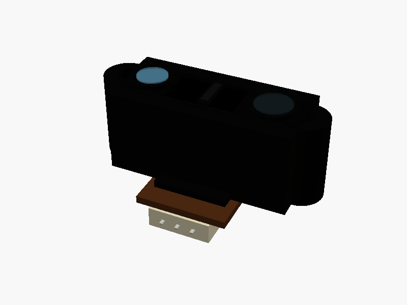
/*
  Sharp GP2Y0A21YK0F outline model
  Unit: mm

  Coordinate system:
    X : sensor width
    Y : body height
    Z : optical/front direction is +Z
        PWB / connector / mounting side is -Z

  Origin:
    Center of main body case, not including connector protrusion.
*/

$fn = 72;
eps = 0.02;

// ---- Main dimensions from datasheet / simplified outline ----
body_w = 29.5;        // main case width
body_h = 13.0;        // lens-case height
body_d = 13.5;        // main body depth

total_w = 37.0;       // overall width including mounting ears
lug_r = 3.75;         // R3.75 mounting ears
lug_x = total_w/2 - lug_r;
mount_hole_d = 3.2;   // dia. 3.2 hole

// Lens center positions.
// Datasheet: left lens center is *4.5 from left case edge,
// lens center pitch is *20±0.1.
lens_left_x  = -body_w/2 + 4.5;
lens_right_x = lens_left_x + 20.0;
lens_mid_x   = (lens_left_x + lens_right_x) / 2;

front_z = body_d/2;
back_z  = -body_d/2;

// ---- Appearance colors ----
case_col   = [0.015, 0.015, 0.014];
panel_col  = [0.001, 0.001, 0.001];
lens_col   = [0.08, 0.12, 0.14, 0.55];
glass_col  = [0.45, 0.75, 0.90, 0.35];
pwb_col    = [0.28, 0.15, 0.06];
conn_col   = [0.86, 0.82, 0.70];
metal_col  = [0.75, 0.75, 0.70];

// ---- Utility modules ----
module cyl_z(d, h) {
    cylinder(d=d, h=h, center=true);
}

module tube_z(d_outer, d_inner, h) {
    difference() {
        cylinder(d=d_outer, h=h, center=true);
        cylinder(d=d_inner, h=h + 0.2, center=true);
    }
}

module rectangular_frame(w, h, bar, depth) {
    union() {
        translate([0,  h/2 - bar/2, 0]) cube([w, bar, depth], center=true);
        translate([0, -h/2 + bar/2, 0]) cube([w, bar, depth], center=true);
        translate([-w/2 + bar/2, 0, 0]) cube([bar, h, depth], center=true);
        translate([ w/2 - bar/2, 0, 0]) cube([bar, h, depth], center=true);
    }
}

// 2D outline of main body + circular mounting ears
module body_outline_2d() {
    union() {
        square([body_w, body_h], center=true);
        translate([-lug_x, 0]) circle(r=lug_r);
        translate([ lug_x, 0]) circle(r=lug_r);
    }
}

// ---- Main plastic case ----
module main_case() {
    color(case_col)
    difference() {
        // Extruded front outline
        linear_extrude(height=body_d, center=true, convexity=10)
            body_outline_2d();

        // Mounting holes through the case, front-to-back
        for (sx = [-1, 1]) {
            translate([sx * lug_x, 0, 0])
                cyl_z(mount_hole_d, body_d + 2);
        }

        // Shallow front recess around optical window
        translate([lens_mid_x, 0, front_z - 0.35 + eps])
            cube([26.0, 8.4, 0.70], center=true);
    }
}

// ---- Front optical face: emitter / detector lenses ----
module front_optics() {
    // Recessed dark panel
    color(panel_col)
    translate([lens_mid_x, 0, front_z - 0.68])
        cube([25.6, 8.0, 0.08], center=true);

    // Slight raised rim around the optical window
    color(case_col)
    translate([lens_mid_x, 0, front_z + 0.08])
        rectangular_frame(26.2, 8.6, 0.65, 0.18);

    // Left emitter square pocket
    color([0.01, 0.01, 0.01])
    translate([lens_left_x, 0, front_z + 0.12])
        cube([7.5, 7.5, 0.22], center=true);

    // Left emitter circular bezel
    color(case_col)
    translate([lens_left_x, 0, front_z + 0.45])
        tube_z(7.0, 5.15, 0.70);

    // Left emitter lens / dark window
    color(glass_col)
    translate([lens_left_x, 0, front_z + 0.84])
        cyl_z(5.0, 0.28);

    // Right detector rectangular pocket
    color([0.01, 0.01, 0.01])
    translate([lens_right_x, 0, front_z + 0.12])
        cube([10.0, 7.2, 0.22], center=true);

    // Right detector circular bezel
    color(case_col)
    translate([lens_right_x, 0, front_z + 0.45])
        tube_z(7.4, 6.0, 0.70);

    // Right detector lens
    color(lens_col)
    translate([lens_right_x, 0, front_z + 0.84])
        cyl_z(5.9, 0.30);

    // Small center molded details
    color(case_col)
    translate([lens_mid_x, 0, front_z + 0.20])
        cube([2.0, 6.8, 0.30], center=true);

    color([0.05, 0.05, 0.05])
    translate([lens_mid_x, 0, front_z + 0.42])
        cube([1.2, 5.2, 0.16], center=true);
}

// ---- Back / PWB / connector side, facing -Z ----
module back_pwb_connector() {
    // PWB, visible on mounting side
    pwb_w = 14.75;
    pwb_h = 7.0;
    pwb_t = 1.2;

    color(pwb_col)
    translate([0, -8.35, back_z - pwb_t/2])
        cube([pwb_w, pwb_h, pwb_t], center=true);

    // Connector housing.
    // Datasheet connector width callout: 10.1
    conn_w = 10.1;
    conn_h = 5.9;
    conn_d = 3.3;

    color(conn_col)
    translate([0, -9.35, back_z - pwb_t - conn_d/2])
        cube([conn_w, conn_h, conn_d], center=true);

    // Socket dark opening on -Z side
    socket_z = back_z - pwb_t - conn_d - 0.035;

    color([0.02, 0.02, 0.018])
    translate([0, -9.35, socket_z])
        cube([8.3, 3.7, 0.08], center=true);

    // Three connector contacts / holes
    for (px = [-2.54, 0, 2.54]) {
        color(metal_col)
        translate([px, -9.35, socket_z - 0.06])
            cyl_z(0.72, 0.12);
    }

    // Three solder / terminal tails
    for (px = [-2.54, 0, 2.54]) {
        color(metal_col)
        translate([px, -12.10, back_z - pwb_t - conn_d/2])
            cube([0.55, 2.1, 0.35], center=true);
    }
}

// ---- Back-side molded lower support / connector boss ----
module connector_boss() {
    color(case_col)
    translate([0, -7.35, back_z + 0.15])
        cube([12.0, 2.4, 2.0], center=true);
}

// ---- Small molded stamp on top surface ----
module molded_stamp() {
    // Kept shallow so the part still remains primarily an outline model.
    color([0.18, 0.18, 0.17])
    translate([0, body_h/2 + 0.035, 0.5])
        rotate([90, 0, 0])
            linear_extrude(height=0.06, center=true, convexity=4)
                text("SHARP", size=2.2, halign="center", valign="center",
                     font="Liberation Sans:style=Bold");
}

// ---- Complete sensor ----
module GP2Y0A21YK0F() {
    main_case();
    front_optics();
    connector_boss();
    back_pwb_connector();
    molded_stamp();
}

// Render model
GP2Y0A21YK0F(); パラメータ (7) —
スライダを動かすと openscad-wasm で再レンダリング
prompt
添付画像は Sharp 製測距センサ GP2Y0A21YK0F のデータシートのページです。
OpenSCAD でモデリングしてください。

座標系: 単位 mm、本体の中心を原点とし、取付面(PWB / コネクタ側)を -Z に向ける。

完成したコード全体を ```openscad ... ``` のフェンスで囲んで出力してください。