vibe-openscad

tier-4-gp2y0a21yk / google/gemma-4-e2b

1 run / 累計 13.7s / 累計 $0

google (self-hosted) gemma-4-e2b pdf-page

bare (provider default effort)

run detail →
render
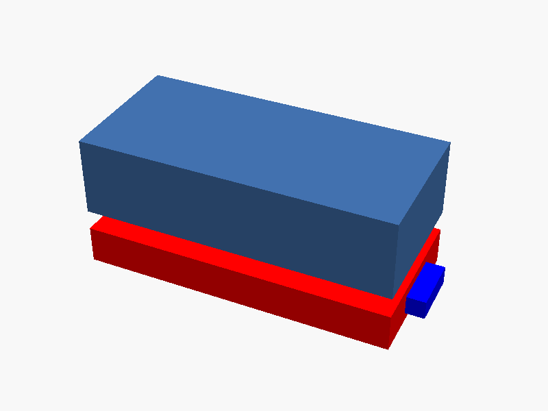
no render
render_error 13.7s · 719/1876t
openscad stl render failed (exit 1): ERROR: Parser error: syntax error in file ../../../../../tmp/render-Pbnghd/input.scad, line 36
Can't parse file '/tmp/render-Pbnghd/input.scad'!

SCAD (90 lines)
// Sharp GP2Y0A21YK0F External Dimensions Modeling (Based on Datasheet 2 Page)

// Coordinate System: Origin at body center. +Z is up, +Y is forward. Units are mm.

// --- Dimensions extracted from the datasheet for reference ---
// Note: These dimensions are interpreted based on the provided schematic and outline dimensions.
// The overall structure is defined by a main body, a linkage bar, and protruding lenses.

// Main Body Parameters (Interpreted from 'Outline Dimensions')
Body_Length = 37.1; // Overall length/depth reference
Body_Width = 27.0;   // Overall width reference
Body_Thickness = 16.7; // Thickness reference (This might be the thickness of the main housing)

Linkage_Bar_Length = 45.8; // Reference dimension for the linkage section length (from side view)

// Lens Parameters (Relative placement on top)
Lens_Diameter = 10.3;    // Diameter of the upper lens/window feature
Lens_Protrusion_Z = Body_Thickness + Lens_Diameter / 2; // Position where lenses protrude upwards

Linkage_Bar_Height = 3.5; // Reference dimension for the linkage bar thickness (estimated from context)
Cable_Exit_Cutout_Size = 10.3; // Dimension related to cable exit/attachment points

// --- Main Body Modeling (The housing block) ---
Module_Body() {
    // Center at (0, 0, 0)
    cube([Body_Width, Body_Length, Body_Thickness], center = true);
}

// --- Lens Modeling (Protruding above the body) ---
Module_Lenses() {
    // Place the lenses centered on the top surface (+Z direction)
    Lens_Radius = Lens_Diameter / 2;
    Lens_Z_Offset = Body_Thickness + (Body_Width / 2); // Position them relative to the origin

    // Light side lens (e.g., Receiver/Emitter area)
    translate([0, 0, Lens_Z_Offset], rotation=()) {
        cylinder(r=Lens_Radius, h=1, center=true);
    }

    // Other potential features (based on the description of separate light components)
    // Since the diagram shows a unified outer shape, we define the top surface based on the widest parts.
}

// --- Linkage Bar Modeling (Extending below the main body) ---
Module_Linkage_Bar() {
    // Position the linkage bar extending downward from the center of the body's length (+Y direction)
    linkage_offset = Body_Length / 2 - Linkage_Bar_Length / 2;

    translate([0, linkage_offset, 0]) {
        cube([Body_Width, Linkage_Bar_Length, Linkage_Bar_Height], center = true);
    }
}


// --- Cable Modeling (Simplified as a round rod) ---
Module_Cable() {
    Cable_Radius = 2.5; // Simplified radius for the cable representation
    Cable_Length = Body_Length;

    // Positioned along one side or defined by external exit points
    translate([Body_Width / 2 + Cable_Radius, 0, Cable_Length / 2]) {
        cylinder(r=Cable_Radius, h=Cable_Length);
    }
}


// --- Assembly ---
module GP2Y0A21YK0F_Model() {
    // 1. Main Body (Block)
    Module_Body();

    // 2. Linkage Bar (Attached to the lower part of the body)
    Module_Linkage_Bar();

    // 3. Lenses (Protrusion on top)
    Module_Lenses();

    // 4. Cable (Simplified representation)
    Module_Cable();

    // Optional: Define mounting holes/cutouts based on the linkage bar area (for visualization purposes)
    /*
    color("red")
    translate([0, Body_Length / 2 - Linkage_Bar_Length / 2, Linkage_Bar_Height / 2]) {
        cube([Body_Width * 0.5, Cable_Exit_Cutout_Size, Linkage_Bar_Height * 2], center = true);
    }
    */
}

GP2Y0A21YK0F_Model();

prompt

添付の Sharp 製測距センサ GP2Y0A21YK0F のデータシート 2 ページ目には
本体の外形寸法図(External dimensions)が描かれています。図を読み取り、
OpenSCAD でセンサの外形をモデリングしてください。

※ 同じ Sharp の GP2Y0D413K0F とは別モデルです:
- レンジ: 10〜80cm(アナログ電圧出力)
- パッケージ:
  - 本体は横長(乗っているレンズ部 + 連結バー部分の2塊で構成)
  - 連結部にケーブル取り出し穴 + 取付穴2個
  - 受光・発光のレンズが本体上部から飛び出している
- コネクタはケーブル(JST PHR-3)で出る、本体下部に直付けではない

含めるべき部位:
- レンズ部本体ケース(直方体に近い、上部にレンズ突起)
- 発光側レンズと受光側レンズ(上面に並ぶ円形 / 矩形の窓)
- 連結バー(レンズ部の下方向に伸びる薄い板状の延長部)
- 連結バーにある取付穴 2 つ + ケーブル取り出しの切欠き
- ケーブル(PCB / コネクタの代わりに丸棒で簡易表現で可)

寸法:
- 図中のミリメートル数値に従ってください
- "*" 印が付いた寸法はレンズ中心位置を示す参照寸法です
- 括弧 `( )` で囲まれた値は参考寸法
- 未指定許容差 ±0.3 mm

座標系:
- 本体の中心が原点。+Z は上方向(レンズが上面)、+Y は前方
- 単位は mm

内部の IC や回路素子はモデリング不要、外形だけで十分です。
完成したコード全体を ```openscad ... ``` のフェンスで囲んで出力してください。
コードのみで、追加の説明は不要です。