tier-4-gp2y0a21yk / gemma-4-26b-a4b-it
1 run / 累計 190.8s / 累計 $0
gemini gemma 4 26b a4b pdf-page
bare (provider default effort)
run detail → render
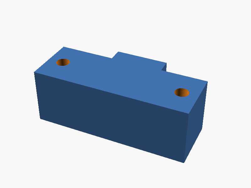
// Sharp GP2Y0A21YK0F Distance Sensor Modeling
// Units: mm

$fn = 50; // 解像度

// --- Dimensions from Datasheet ---
width_total = 37.0;
hole_spacing = 29.5;
hole_diameter = 3.2;

height_total = 13.5;
height_main_body = 13.0; // Side view indicates main block height
body_depth = 13.0;       // Estimated from side view proportions

lens_case_depth = 6.3;
lens_case_width = 13.0;  // Estimated from side view
lens_case_height = 10.0; // Estimated from side view

connector_width = 14.75;
connector_depth = 3.3;   // From (3.3) reference in datasheet
connector_thickness = 1.2; // Estimated base thickness

// --- Modeling ---

module sensor_gp2y0a21() {
    difference() {
        union() {
            // 1. Main Body (The rectangular housing)
            // Placed so the mounting surface is towards -Z
            // Center of the 37x13x13.5 bounding box is the origin
            translate([0, 0, 0])
                cube([width_total, body_depth, height_total], center=true);

            // 2. Lens Case (Protruding in +Y direction)
            translate([0, body_depth/2 + lens_case_depth/2, 0])
                cube([lens_case_width, lens_case_depth, lens_case_height], center=true);

            // 3. Connector/PWB Base (At the -Z side)
            // Positioned at the bottom face of the sensor
            translate([0, -connector_depth/2, -height_total/2 + connector_thickness/2])
                cube([connector_width, connector_depth, connector_thickness], center=true);
        }

        // 4. Mounting Holes (Subtraction)
        // Holes are located on the X-axis at +/- hole_spacing/2
        translate([hole_spacing/2, 0, 0])
            cylinder(d=hole_diameter, h=height_total + 2, center=true);
        translate([-hole_spacing/2, 0, 0])
            cylinder(d=hole_diameter, h=height_total + 2, center=true);

        // 5. Connector pin area cutout (Optional refinement)
        // Creates a small notch for the connector pins on the bottom
        translate([0, 0, -height_total/2 - 0.1])
            cube([10.1, 10, 1], center=true);
    }
}

// Execute modeling
sensor_gp2y0a21();

// --- Reference Axis Helper (Optional, for visualization) ---
// Uncomment below to see axes
/*
%translate([0,0,0]) cube([1,1,1], center=true); // Origin
*/ パラメータ (12) —
スライダを動かすと openscad-wasm で再レンダリング
prompt
添付画像は Sharp 製測距センサ GP2Y0A21YK0F のデータシートのページです。
OpenSCAD でモデリングしてください。

座標系: 単位 mm、本体の中心を原点とし、取付面(PWB / コネクタ側)を -Z に向ける。

完成したコード全体を ```openscad ... ``` のフェンスで囲んで出力してください。