tier-4-gp2y0a21yk / claude-sonnet-5
1 run / 累計 251.0s / 累計 $0.2309
claude sonnet 5 pdf-page
bare (provider default effort)
run detail → render
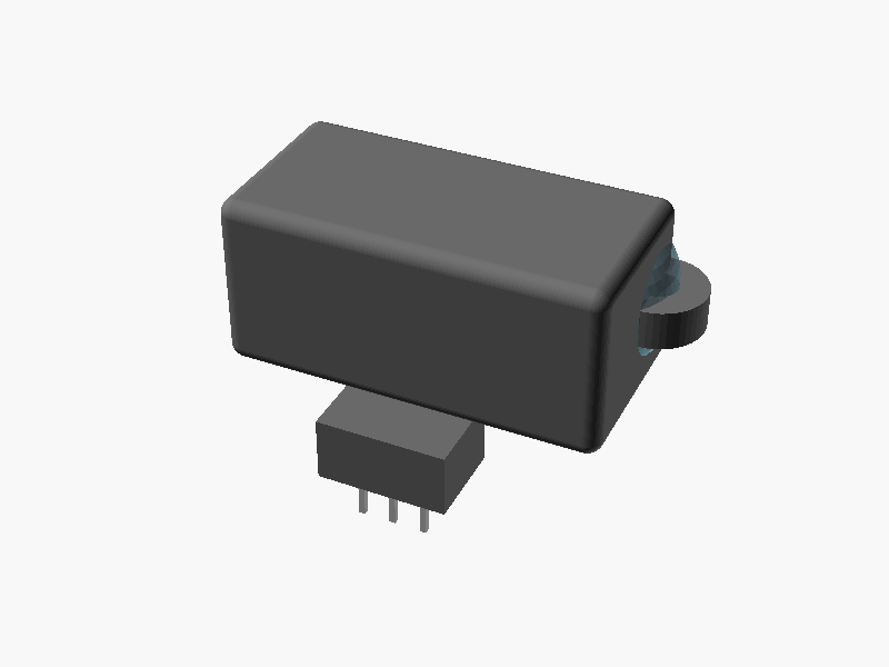
// =====================================================================
//  SHARP GP2Y0A21YK0F  距離測定センサ 簡易外形モデル
//  単位: mm
//  座標系: 原点 = 本体(メインハウジング)の中心
//          -Z方向 = 取付面(PWB/コネクタ側)
//          +Y方向 = レンズ(受光/発光)が向く測距方向
//          X方向  = 発光/受光レンズが並ぶ方向(左右)
//
//  注記:
//   - データシートに明記された寸法はそのまま採用
//     (37, 29.5, R3.75, φ3.2, 20±0.1, 4.5, 13, 13.5, 10.1, 1.2 など)
//   - 奥行き(Y)方向やコネクタ突出量、レンズ突出量など
//     図面から一意に読み取れない値は「推定値」として
//     妥当な値を仮定している(コメントに明記)。
// =====================================================================

$fn = 48;

// ---------------- データシート記載の寸法 ----------------
overall_width   = 37;      // 取付耳 端-端 全幅 (X)
body_width      = 29.5;    // 本体幅 (X)
tab_r           = 3.75;    // 取付耳 半径 R3.75
tab_hole_d      = 3.2;     // 取付穴 φ3.2
lens_spacing    = 20;      // 発光-受光 レンズ中心間距離 (X) 20±0.1
lens_offset_x   = 4.5;     // 左端から発光レンズ中心までの距離(*印)
body_height     = 13.5;    // 本体高さ (Z) ※側面図の13ともほぼ整合
conn_width      = 10.1;    // コネクタハウジング幅 (X)
pwb_thickness   = 1.2;     // PWB厚み(参考値)

// ---------------- 推定寸法(図面から一意に確定できない値) ----------------
body_depth        = 14.75; // 本体奥行き (Y) : 上面図の奥行き系寸法を採用
tab_thickness     = 3;     // 取付耳の厚み(Z方向)
emitter_lens_d    = 9;     // 発光側レンズ外径(推定)
detector_lens_d   = 13;    // 受光側(PSD)レンズ外径(推定、発光側より大きい)
lens_protrusion   = 3;     // レンズドームの前面からの突出量(推定)
conn_protrusion   = 4;     // コネクタが本体背面より後方へ突出する量(推定)
conn_depth_embed  = 3;     // コネクタが本体側に食い込む奥行き(結合用)
conn_height       = 5;     // コネクタハウジングが本体底面より下へ出る高さ(推定)
pin_length        = 4;     // コネクタピンの突出長さ(推定)
pin_pitch         = 2.5;   // ピン間隔(推定, 3ピン)
pin_size          = 0.5;   // ピン断面サイズ(推定)
edge_round_r      = 1.2;   // 本体の面取り半径(見栄え用)

// ---------------- 派生値 ----------------
lens_center_x_e = -body_width/2 + lens_offset_x;
lens_center_x_d = lens_center_x_e + lens_spacing;

front_y  =  body_depth/2;   // 本体前面(レンズ側)
back_y   = -body_depth/2;   // 本体背面(コネクタ側)
top_z    =  body_height/2;
bottom_z = -body_height/2;

// =====================================================================
//  部品モジュール
// =====================================================================

// 角を丸めた箱(見栄え用)
module rounded_box(size, r) {
    hull() {
        for (sx = [-1, 1])
            for (sy = [-1, 1])
                for (sz = [-1, 1])
                    translate([sx*(size[0]/2 - r),
                               sy*(size[1]/2 - r),
                               sz*(size[2]/2 - r)])
                        sphere(r = r);
    }
}

// メインハウジング(本体中心が原点)
module main_housing() {
    rounded_box([body_width, body_depth, body_height], edge_round_r);
}

// 取付耳 (左右, R3.75, φ3.2の穴付き)
module mounting_ear(x_sign) {
    ex = x_sign * body_width / 2;   // 本体端に耳の中心を配置 → 全幅37mmと整合
    ey = front_y - tab_r;           // 前面付近に配置(推定)
    translate([ex, ey, 0])
        difference() {
            cylinder(r = tab_r, h = tab_thickness, center = true);
            cylinder(d = tab_hole_d, h = tab_thickness + 2, center = true);
        }
}

// レンズ(発光/受光) ドーム状の突起
module lens_dome(x, d) {
    r = d / 2;
    // 球の中心を前面よりやや内側に置き、lens_protrusion分だけ前方に突出させる
    translate([x, front_y + lens_protrusion - r, 0])
        sphere(r = r);
}

// コネクタハウジング(本体背面下部より後方・下方へ突出)
module connector_housing() {
    conn_total_depth = conn_protrusion + conn_depth_embed;
    conn_y_center = back_y - conn_protrusion/2 + conn_depth_embed/2;
    conn_z_center = bottom_z - conn_height/2;
    translate([0, conn_y_center, conn_z_center])
        cube([conn_width, conn_total_depth, conn_height], center = true);
}

// コネクタピン(3ピン, -Z方向に突出)
module connector_pins() {
    pin_y = back_y - conn_protrusion/2; // コネクタ手前寄りに配置(推定)
    pin_z_top = bottom_z - conn_height;
    for (i = [-1, 0, 1]) {
        translate([i * pin_pitch, pin_y, pin_z_top - pin_length/2])
            cube([pin_size, pin_size, pin_length], center = true);
    }
}

// =====================================================================
//  全体組み立て
// =====================================================================
module GP2Y0A21YK0F() {

    // --- 本体樹脂ケース(導電性樹脂ABS) ---
    color("DimGray")
    union() {
        main_housing();
        mounting_ear(1);
        mounting_ear(-1);
        connector_housing();
    }

    // --- レンズ(可視光カットのアクリル樹脂) ---
    color("SkyBlue", 0.55)
    union() {
        lens_dome(lens_center_x_e, emitter_lens_d);
        lens_dome(lens_center_x_d, detector_lens_d);
    }

    // --- コネクタピン ---
    color("Silver")
    connector_pins();
}

GP2Y0A21YK0F(); パラメータ (21) —
スライダを動かすと openscad-wasm で再レンダリング
prompt
添付画像は Sharp 製測距センサ GP2Y0A21YK0F のデータシートのページです。
OpenSCAD でモデリングしてください。

座標系: 単位 mm、本体の中心を原点とし、取付面(PWB / コネクタ側)を -Z に向ける。

完成したコード全体を ```openscad ... ``` のフェンスで囲んで出力してください。