tier-4-gp2y0a21yk / claude-sonnet-4-6
1 run / 累計 48.9s / 累計 $0.0482
claude sonnet 4.6 pdf-page
bare (provider default effort)
run detail → render
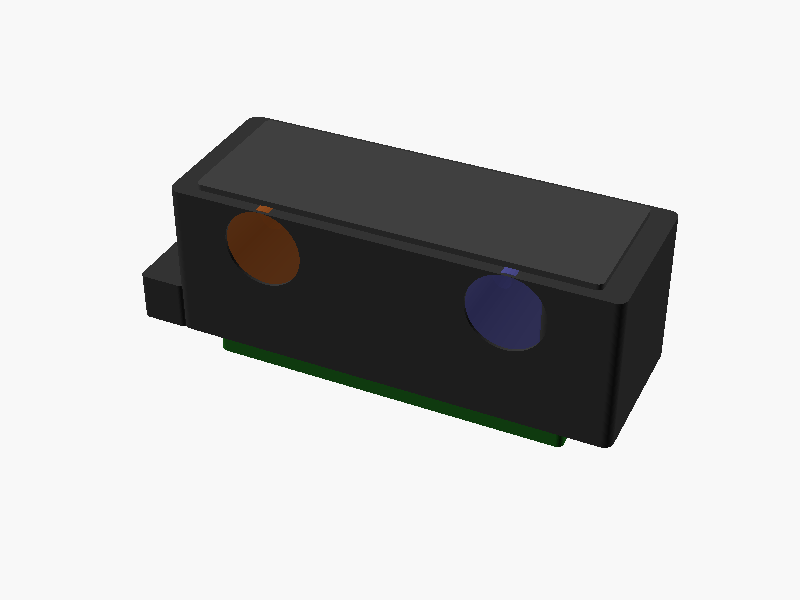
// Sharp GP2Y0A21YK0F Distance Measuring Sensor
// Unit: mm
// Origin: center of main body
// -Z direction: mounting face (PWB/connector side)

$fn = 64;

// ===== Main Dimensions =====
body_w  = 37.0;   // X: total width
body_d  = 13.5;   // Y: depth (front-back)
body_h  = 13.0;   // Z: height of main body (including lens case top)

pwb_w   = 29.5;   // PWB width (centered)
pwb_d   = body_d;
pwb_h   = 1.2;    // PWB thickness

// Body is split into main block and lens case protrusion
main_h  = 8.4;    // main body height (below lens case level) -- from datasheet side view

// Lens case (right side)
lens_w  = 6.3;    // lens case width (X)
lens_h  = 13.0;   // lens case height (Z)
lens_d  = body_d; // same depth

// Mounting holes
hole_d      = 3.2;
hole_offset = 20.0;  // center-to-center distance between holes (X direction)
// Left hole from left edge: 4.5mm  → center X = -body_w/2 + 4.5
// Right hole from left edge: 4.5+20 = 24.5mm → center X = -body_w/2 + 24.5
hole_x_left  = -body_w/2 + 4.5;
hole_x_right = hole_x_left + hole_offset;
hole_y       = 0;  // centered in depth
hole_z_bot   = -body_h/2;  // bottom of body (mounting face side)

// Connector
conn_w  = 10.0;  // approximate connector width (3 pins, ~10mm)
conn_d  = 7.5;   // connector depth from side view bottom view
conn_h  = 3.3;   // protrudes below PWB (from datasheet: 3.3 ref)
// Connector position: bottom view shows 7.5 from left, 4.15 wide block, 16.3 from right
// connector center X from left edge of body: 7.5 + (body_w - 7.5 - 16.3)/2 ?
// Bottom view: 7.5 | 4.15 | 16.3 → total = 7.5+4.15+16.3 = 27.95... not quite 37
// Let's place connector centered at X = -body_w/2 + 7.5 + 4.15/2 = -18.5 + 9.575 = -8.925
conn_cx = -body_w/2 + 7.5 + 4.15/2;
conn_cy = 0;

// Lens parameters
lens_r  = 3.75;  // R3.75

// Emitter lens center: from left edge 4.5mm? (same as hole), but lenses are separate
// From top view: emitter left side, detector center area
// Emitter center X: -body_w/2 + 4.5 + lens_r ≈ left side
// Detector center X: around center-right of main body
emitter_cx = -body_w/2 + 4.5 + lens_r;  // ~-14.25
// Detector at ~20mm from left edge center
detector_cx = -body_w/2 + 4.5 + hole_offset/2; // -18.5+14.5 = ~-4 ?
// Let's use datasheet: φ3.2 hole for detector near center
// emitter hole at left, detector hole slightly right of center
// Simplified placement:
emitter_x   = -body_w/2 + 4.5 + lens_r;  // ≈ -14.25
detector_x  =  emitter_x + hole_offset;   // +5.75 (using 20mm between holes as guide)

lens_z_top  =  body_h/2;  // flush with top of body
lens_cy     =  0;          // centered in Y

// Colors
color_body      = [0.2, 0.2, 0.2, 1.0];  // dark gray ABS
color_pwb       = [0.1, 0.4, 0.1, 1.0];  // green PCB
color_lens      = [0.15, 0.15, 0.15, 1.0];
color_connector = [0.8, 0.7, 0.3, 1.0];  // yellowish connector

// ===== Helper: rounded box =====
module rounded_box(w, d, h, r=0.5) {
    hull() {
        for (xi = [-1, 1]) for (yi = [-1, 1]) {
            translate([xi*(w/2 - r), yi*(d/2 - r), 0])
                cylinder(r=r, h=h, center=true);
        }
    }
}

// ===== Main body block =====
module main_body() {
    color(color_body) {
        difference() {
            // Main rectangular body
            translate([0, 0, 0])
                rounded_box(body_w, body_d, body_h, r=1.0);

            // Mounting hole (left)
            translate([hole_x_left, hole_y, 0])
                cylinder(d=hole_d, h=body_h+2, center=true);

            // Mounting hole (right)
            translate([hole_x_right, hole_y, 0])
                cylinder(d=hole_d, h=body_h+2, center=true);

            // Cutout for lens openings (emitter)
            translate([emitter_x, 0, body_h/2 - lens_r + 0.5])
                rotate([90, 0, 0])
                    cylinder(d=lens_r*2 - 1.0, h=body_d+2, center=true);

            // Cutout for lens openings (detector)
            translate([detector_x, 0, body_h/2 - lens_r + 0.5])
                rotate([90, 0, 0])
                    cylinder(d=lens_r*2 - 1.0, h=body_d+2, center=true);
        }
    }
}

// ===== Lens case (elevated portion on right side) =====
module lens_case() {
    // The lens case is a protrusion on the right side of the body
    // It extends slightly above the main body height
    lc_x_center = body_w/2 - lens_w/2;
    lc_extra_h  = 0;  // same height as body in this model
    color(color_body)
        translate([lc_x_center, 0, 0])
            rounded_box(lens_w, body_d, lens_h, r=0.8);
}

// ===== Lenses =====
module emitter_lens() {
    color([0.6, 0.3, 0.1, 0.9])  // IR LED: orange-ish
    translate([emitter_x, 0, body_h/2 - lens_r + 0.3])
        rotate([90, 0, 0])
            cylinder(d=lens_r*2 - 0.5, h=body_d - 0.5, center=true);
}

module detector_lens() {
    color([0.3, 0.3, 0.6, 0.85])  // PSD: blue-ish
    translate([detector_x, 0, body_h/2 - lens_r + 0.3])
        rotate([90, 0, 0])
            cylinder(d=lens_r*2 - 0.5, h=body_d - 0.5, center=true);
}

// ===== PWB (printed wiring board) =====
module pwb() {
    color(color_pwb)
    translate([0, 0, -body_h/2 - pwb_h/2])
        rounded_box(pwb_w, pwb_d, pwb_h, r=0.5);
}

// ===== Connector =====
module connector() {
    // 3-pin JST connector protruding below PWB
    pin_pitch = 2.5;
    conn_body_w = 3 * pin_pitch + 2.0;  // ~9.5
    conn_body_d = 6.0;
    conn_body_h = conn_h;

    color(color_connector)
    translate([conn_cx, 0, -body_h/2 - pwb_h - conn_body_h/2])
        rounded_box(conn_body_w, conn_body_d, conn_body_h, r=0.3);

    // Pins
    color([0.8, 0.8, 0.8])
    for (i = [-1, 0, 1]) {
        translate([conn_cx + i * pin_pitch, 0, -body_h/2 - pwb_h - conn_body_h - 2.5/2])
            cylinder(d=0.5, h=2.5, center=true);
    }
}

// ===== Label bump (stamp area on top) =====
module stamp_bump() {
    color([0.25, 0.25, 0.25])
    translate([0, 0, body_h/2 + 0.5/2])
        rounded_box(body_w - 4, body_d - 2, 0.5, r=0.5);
}

// ===== Mounting tab on left side =====
// From top view there's a notch/tab on the far left
module left_tab() {
    tab_w = 4.0;
    tab_d = body_d;
    tab_h = 4.0;
    color(color_body)
    translate([-body_w/2 - tab_w/2 + 0.5, 0, -body_h/2 + tab_h/2])
        rounded_box(tab_w, tab_d, tab_h, r=0.5);
}

// ===== Assemble =====
main_body();
lens_case();
emitter_lens();
detector_lens();
pwb();
connector();
stamp_bump();
left_tab(); パラメータ (17) —
スライダを動かすと openscad-wasm で再レンダリング
prompt
添付画像は Sharp 製測距センサ GP2Y0A21YK0F のデータシートのページです。
OpenSCAD でモデリングしてください。

座標系: 単位 mm、本体の中心を原点とし、取付面(PWB / コネクタ側)を -Z に向ける。

完成したコード全体を ```openscad ... ``` のフェンスで囲んで出力してください。