vibe-openscad

tier-4-gp2y0a21yk / claude-haiku-4-5-20251001

1 run / 累計 10.5s / 累計 $0.0095

claude haiku 4.5 2025-10-01 pdf-page

bare (provider default effort)

run detail →
render
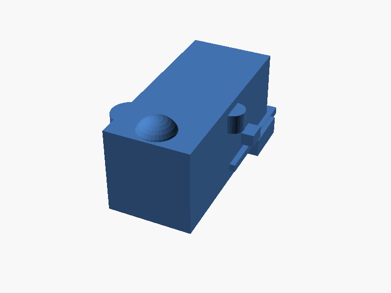
bare render of tier-4-gp2y0a21yk
loading STL…
success 10.5s · 2211/1464t · $0.0095
SCAD (119 lines)
// Sharp GP2Y0A21YK0F Distance Sensor - OpenSCAD Model

// Parameters
$fn = 32;

// Main body dimensions
body_length = 37;      // Total length of main body
body_width = 29.5;     // Total width of main body
body_height = 12.3;    // Height of main body

// Lens positions (from datasheet)
lens_emitter_x = -4.5;   // Light emitter X position (reference)
lens_detector_x = 20 + 0.1; // Light detector X position (reference)
lens_y = 0;            // Lens Y position (center)

// Lens dimensions
lens_emitter_diameter = 3.5;  // Emitter lens diameter
lens_detector_width = 3.5;    // Detector lens width
lens_detector_height = 7.2;   // Detector lens height
lens_protrusion = 2.0; // How much lenses protrude above body

// Connection bar dimensions
bar_length = 16.1;     // Length of connection bar
bar_width = 14.75;     // Width of connection bar
bar_height = 1.2;      // Thickness of connection bar
bar_y_offset = -14.75 / 2; // Starting Y position of bar from body

// Mounting holes
hole_diameter = 1.2;
hole_left_x = -7.5 / 2;
hole_right_x = 7.5 / 2;
hole_y = -4.15;  // Y position on the bar

// Cable cutout
cable_cutout_width = 4.15;
cable_cutout_height = 3.1;
cable_cutout_y = -9.4; // Approximate position on bar

// Cable representation
cable_diameter = 1.5;
cable_length = 10;
cable_z_position = -bar_height / 2 - cable_diameter / 2;

// Main body with lens protrusions
module main_body() {
    // Base rectangular body
    translate([0, 0, 0])
        cube([body_length, body_width, body_height], center = true);
    
    // Emitter lens protrusion (circular)
    translate([lens_emitter_x, lens_y, body_height / 2 + lens_protrusion / 2])
        cylinder(h = lens_protrusion, r = lens_emitter_diameter / 2, center = true);
    
    // Detector lens protrusion (rectangular)
    translate([lens_detector_x, lens_y, body_height / 2 + lens_protrusion / 2])
        cube([lens_detector_width, lens_detector_height, lens_protrusion], center = true);
}

// Lens windows on top surface
module lens_windows() {
    // Emitter window (circular)
    translate([lens_emitter_x, lens_y, body_height / 2 + 0.1])
        cylinder(h = 0.5, r = lens_emitter_diameter / 2 - 0.2, center = true, $fn = 16);
    
    // Detector window (rectangular)
    translate([lens_detector_x, lens_y, body_height / 2 + 0.1])
        cube([lens_detector_width - 0.4, lens_detector_height - 0.4, 0.5], center = true);
}

// Connection bar with features
module connection_bar() {
    difference() {
        // Base bar
        translate([0, bar_y_offset - bar_width / 2, -body_height / 2 - bar_height / 2])
            cube([bar_length, bar_width, bar_height], center = true);
        
        // Left mounting hole
        translate([hole_left_x, bar_y_offset - hole_y, -body_height / 2 - bar_height / 2])
            cylinder(h = bar_height + 1, r = hole_diameter / 2, center = true, $fn = 16);
        
        // Right mounting hole
        translate([hole_right_x, bar_y_offset - hole_y, -body_height / 2 - bar_height / 2])
            cylinder(h = bar_height + 1, r = hole_diameter / 2, center = true, $fn = 16);
        
        // Cable cutout
        translate([0, bar_y_offset - cable_cutout_y, -body_height / 2 - bar_height / 2])
            cube([cable_cutout_width, cable_cutout_height, bar_height + 1], center = true);
    }
}

// Cable representation (simplified as cylinder)
module cable() {
    translate([0, bar_y_offset - cable_cutout_y, cable_z_position])
        cylinder(h = cable_length, r = cable_diameter / 2, center = true, $fn = 16);
}

// Complete sensor assembly
module gp2y0a21yk0f() {
    // Main body
    main_body();
    
    // Connection bar with holes and cutout
    connection_bar();
    
    // Cable
    cable();
}

// Render the sensor
gp2y0a21yk0f();

// Optional: Add reference planes/axes for debugging
// (uncomment to visualize coordinate system)
/*
%cube([0.5, 0.5, 0.5], center = true); // Origin marker
translate([5, 0, 0]) %cube([10, 0.5, 0.5], center = true); // X axis
translate([0, 5, 0]) %cube([0.5, 10, 0.5], center = true); // Y axis
translate([0, 0, 5]) %cube([0.5, 0.5, 10], center = true); // Z axis
*/
パラメータ (19)
スライダを動かすと openscad-wasm で再レンダリング

prompt

添付の Sharp 製測距センサ GP2Y0A21YK0F のデータシート 2 ページ目には
本体の外形寸法図(External dimensions)が描かれています。図を読み取り、
OpenSCAD でセンサの外形をモデリングしてください。

※ 同じ Sharp の GP2Y0D413K0F とは別モデルです:
- レンジ: 10〜80cm(アナログ電圧出力)
- パッケージ:
  - 本体は横長(乗っているレンズ部 + 連結バー部分の2塊で構成)
  - 連結部にケーブル取り出し穴 + 取付穴2個
  - 受光・発光のレンズが本体上部から飛び出している
- コネクタはケーブル(JST PHR-3)で出る、本体下部に直付けではない

含めるべき部位:
- レンズ部本体ケース(直方体に近い、上部にレンズ突起)
- 発光側レンズと受光側レンズ(上面に並ぶ円形 / 矩形の窓)
- 連結バー(レンズ部の下方向に伸びる薄い板状の延長部)
- 連結バーにある取付穴 2 つ + ケーブル取り出しの切欠き
- ケーブル(PCB / コネクタの代わりに丸棒で簡易表現で可)

寸法:
- 図中のミリメートル数値に従ってください
- "*" 印が付いた寸法はレンズ中心位置を示す参照寸法です
- 括弧 `( )` で囲まれた値は参考寸法
- 未指定許容差 ±0.3 mm

座標系:
- 本体の中心が原点。+Z は上方向(レンズが上面)、+Y は前方
- 単位は mm

内部の IC や回路素子はモデリング不要、外形だけで十分です。
完成したコード全体を ```openscad ... ``` のフェンスで囲んで出力してください。
コードのみで、追加の説明は不要です。