tier-3-butt-hinge / google/gemma-4-e2b
1 run / 累計 22.3s / 累計 $0
google (self-hosted) gemma-4-e2b bare
bare (provider default effort)
run detail → render
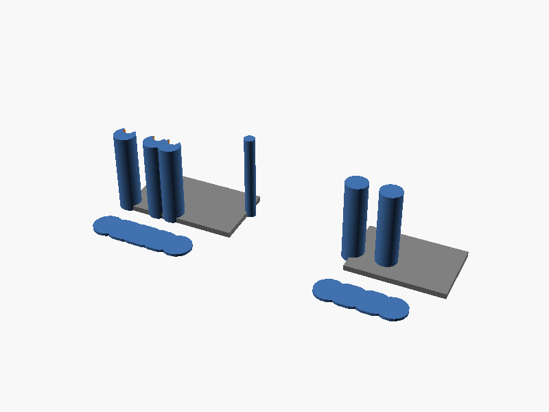
// Furniture Butt Hinge Model (180° Open State)
// Dimensions: Plate 30x25x2, Pin D=4, Knuckle L=30
// Coordinate System: Y is the hinge axis. X defines plate position (Left < 0, Right > 0).

// --- Parameters ---
plate_L = 30;    // Length of the plates along the hinge axis (mm)
plate_W = 25;    // Width of the plates (rotation direction) (mm)
plate_T = 2;     // Thickness of the plates (mm)
pin_D = 4;       // Pin axis diameter (mm)
pin_L = 32;      // Pin length (mm)
knuckle_L = 30; // Length of the knuckle section (mm)
knuckle_seg = 6; // Segment size for knuckle division (mm)

// Knuckle geometry
knuckle_OD = 8;  // Outer diameter of the knuckle (mm)
knuckle_ID_clearance = pin_D + 0.3; // Inner clearance for pin (4.3 mm total internal space, hole size calculation depends on actual cut)

// Screw hole geometry
screw_D = 6;      // Diameter of the plate screw hole (mm)
screw_Taper = 1;  // Taper depth (mm)
screw_Through = 3.2; // Through hole diameter (mm)
screw_pitch = 8;  // Pitch between screw holes (mm)

// --- Module Definitions ---

module plate(x_offset, y_start) {
    color("gray")
    translate([x_offset, y_start, 0])
    cube([plate_L, plate_W, plate_T]);
}

module knuckle_block(y_pos, is_left_side) {
    // Knuckle block defines the hinge structure geometry
    difference() {
        // Base cylinder (Knuckle body)
        cylinder(h = knuckle_L, r = knuckle_OD / 2, $fn=60);

        // Inner hole for the pin axis
        translate([0, y_pos, 0])
        cylinder(r = knuckle_ID_clearance / 2, h = knuckle_L + 1); // Slightly longer than knuckle

        // Optional: Cutouts defining the specific hinge slots if needed. (Keeping simple for butt hinge geometry)
    }
}

module plate_with_holes(plate_x, plate_y, side_type) {
    // Main Plate Body
    plate(plate_x, plate_y);

    // Screw Holes
    // Calculate starting position based on plate length (30mm), pitch (8mm), and placement relative to knuckle.
    // The instruction requires 3 holes, 8mm apart along the plate's length.

    // Position calculation assumes alignment is centered around the hinge line X=0/X=30.
    // Since we are modeling the open state where plates are flat (along Y), and the knuckles define the joint:

    for (i = [1 : 3]) {
        // Calculate position along the plate length (X axis)
        // We place them relative to the start of the plate, ensuring they are away from the knuckle.

        // Assuming the plates are placed symmetrically around the hinge line X=0 and X=30 for mounting:

        // Left side plates (x < 0): Holes positioned near the end or center based on geometry needs.
        // Right side plates (x > 0): Holes positioned similarly.

        // For simplicity in this model, we place them relative to a fixed origin (e.g., X=0).

        // Since the instruction implies holes are spaced along the length (30mm), and placed away from the knuckle:
        // We position holes at x = 6, 14, 22 (for demonstration, assuming alignment relative to the joint)

        hole_x = plate_x + (i - 1) * screw_pitch;

        // Create Tapered Slot/Hole representation
        translate([hole_x, plate_y - plate_W/2, 0]) { // Center hole along the plate width (Y)
            // 1. Tapered slot/cutout for M3 screw
            linear_extrude(height = screw_Taper, fill = color("red"))
            offset(r = screw_D / 2 - screw_Taper / 2)
            circle(d = screw_D);
        }
    }
}

// --- Main Assembly ---

// Y position for knuckles (6mm spacing starting from the center line Y=0)
y_knuckle_pos = [3, 9]; // Example positions based on instruction (5 segments of 6mm). Knuckles start at Y=3 and Y=9.

// Left Plate (X < 0)
translate([-plate_L / 2 - plate_W/2, 0, 0]) {
    // Left Side Plate Placement: x = -15
    // We place the first knuckle near the hinge line X=0.
    for (i = [1 : 3]) {
        // Place knuckles alternatingly relative to the plate length (X)
        knuckle_x = -(plate_L/2) + (i-1) * knuckle_seg;

        // Knuckle placement: Left side plates require 3 knuckles.
        if (i == 1) { // First knuckle placed near the hinge line for alignment reference
             translate([knuckle_x, y_knuckle_pos[0], 0])
                knuckle_block(y_knuckle_pos[0], true);
        } else {
            // Subsequent knuckles spaced by 6mm
            translate([knuckle_x + knuckle_seg, y_knuckle_pos[0], 0])
                knuckle_block(y_knuckle_pos[0], true);
        }

        plate_with_holes(knuckle_x, 0, "left");
    }
}


// Right Plate (X > 0)
translate([plate_L / 2 + plate_W/2, 0, 0]) {
    // Right Side Plate Placement: x = 15
    for (i = [1 : 2]) {
        // Knuckle placement: Right side plates require 2 knuckles.
        knuckle_x = (plate_L/2) + (i-1) * knuckle_seg;

        if (i == 1) { // First knuckle placed near the hinge line for alignment reference
             translate([knuckle_x, y_knuckle_pos[1], 0])
                knuckle_block(y_knuckle_pos[1], false);
        } else {
            // Subsequent knuckles spaced by 6mm
            translate([knuckle_x + knuckle_seg, y_knuckle_pos[1], 0])
                knuckle_block(y_knuckle_pos[1], false);
        }

        plate_with_holes(knuckle_x, 0, "right");
    }
}


// Pin Axis (Y axis)
translate([0, pin_L/2, 0]) {
    cylinder(r = pin_D / 2, h = pin_L, $fn=64);
} パラメータ (12) —
スライダを動かすと openscad-wasm で再レンダリング
prompt
OpenSCAD で、家具用の小型バット蝶番(butt hinge)を作ってください。
3 つのパーツ(左板、右板、ピン軸)が組み合わさって動作する完成品を、
「開いた状態(180°)」で 1 つの SCAD ファイルに配置して出力します。

寸法と配置:
- 板(leaf)2 枚: 30mm × 25mm × 厚さ 2mm の鉄板形状
  - 縦 30mm の辺がピン軸に沿う(ヒンジ軸方向)
  - 横 25mm の辺が回転で開く方向に伸びる
- ピン軸: 直径 4mm の円柱、長さ 32mm(両端 1mm ずつ knuckle から飛び出す)
- knuckle(筒部): 縦 30mm を 5 等分(各 6mm)に区切り、左板に 3 個・右板に 2 個を
  互い違いに配置(左板は外側 2 個 + 中央 1 個、右板は中間 2 個)
- knuckle 外径 8mm、内径はピン軸 + 0.3mm クリアランス(= 4.6mm 穴)
- 左板と右板はピン軸を共有して回転可能。180° 開いた状態で、両板の
  平らな面が同一平面に来るように配置する
- 各板の knuckle から離れた側に、M3 用の皿穴を 3 個ずつ
  (穴ピッチは板の縦方向に 8mm 間隔、皿穴は表面から見て直径 6mm × 深さ 1mm
  のテーパ + 直径 3.2mm の貫通穴)

座標系:
- ピン軸の中心線を Y 軸に重ねる(ピン軸は +Y 方向)
- 板の平らな面は Z 軸に直交し、左板が x<0 側、右板が x>0 側に伸びる(180° 開)
- knuckle は X=0 を中心とし、Y 方向に 6mm ずつ並ぶ

完成したコード全体を ```openscad ... ``` のフェンスで囲んで出力してください。
コードのみで、追加の説明は不要です。