pdf-page/gpt-6-sol / tier-4-gp2y0d413k
success tier 4
pdf-page (gpt 6 sol)
render
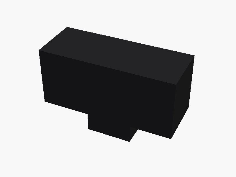
// Sharp GP2Y0D413K0F — 外形図に基づく概略モデル
// 単位: mm
// X: 本体の長手方向
// Y: 光学面の方向(レンズは +Y)
// Z: 本体の高さ方向(PWB・コネクタは -Z)
//
// 原点は、コネクタを除く本体外形の中心。
// データシートに詳細寸法のない凹凸や端子形状は概略表現。

$fn = 64;

body_w = 29.45;
body_d = 11.4;
body_h = 13.05;

front_y = body_d / 2;
body_bottom = -body_h / 2;

emitter_x  = -body_w / 2 + 4.5;
detector_x = emitter_x + 19.7;

connector_w = 10.1;
connector_d = 7.4;
connector_bottom = body_h / 2 - 18.9;

// +Y 方向に向く円柱
module forward_cylinder(r, length, center = false) {
    rotate([-90, 0, 0])
        cylinder(r = r, h = length, center = center);
}

// Y 方向を厚みとする、中央に穴のある矩形枠
module front_frame(w, h, inner_w, inner_h, depth) {
    difference() {
        cube([w, depth, h], center = true);
        cube([inner_w, depth + 0.04, inner_h], center = true);
    }
}

module case_and_connector() {
    color([0.14, 0.14, 0.15])
    difference() {
        union() {
            // 本体
            cube([body_w, body_d, body_h], center = true);

            // 光学面下端のケース継ぎ目/段差
            translate([0, front_y + 0.12, -4.65])
                cube([body_w - 0.3, 0.24, 2.05], center = true);

            // 下向きのコネクタハウジング
            translate([0, -0.2,
                       (body_bottom + 2.0 + connector_bottom) / 2])
                cube([connector_w, connector_d,
                      body_bottom + 2.0 - connector_bottom],
                     center = true);
        }

        // コネクタの開口:-Z 側から掘り込む
        translate([0, -0.2, connector_bottom + 1.13])
            cube([8.0, 5.65, 2.30], center = true);

        // コネクタ前面の小さな切り欠き
        translate([0, 3.51, connector_bottom + 5.25])
            cube([5.5, 0.9, 2.3], center = true);
    }
}

module emitter() {
    // 左側の発光窓
    color([0.08, 0.08, 0.085])
    translate([emitter_x, front_y + 0.17, 0])
        cube([7.7, 0.34, 7.3], center = true);

    color([0.35, 0.35, 0.36])
    translate([emitter_x, front_y + 0.38, 0])
        front_frame(7.35, 7.0, 6.55, 6.2, 0.13);

    color([0.10, 0.10, 0.11])
    translate([emitter_x, front_y + 0.25, 0])
        forward_cylinder(3.05, 1.65);

    color([0.36, 0.36, 0.37])
    translate([emitter_x, front_y + 1.88, 0])
        forward_cylinder(2.76, 0.10);

    color([0.28, 0.31, 0.33])
    translate([emitter_x, front_y + 1.91, 0])
        forward_cylinder(2.38, 0.13);
}

module detector() {
    // 右側の受光窓と、横長のレンズケース
    color([0.085, 0.085, 0.09])
    translate([5.45, front_y + 0.19, 0])
        cube([16.3, 0.38, 7.35], center = true);

    color([0.37, 0.37, 0.38])
    translate([5.45, front_y + 0.43, 0])
        front_frame(15.6, 6.75, 14.7, 5.85, 0.13);

    color([0.12, 0.12, 0.13])
    translate([detector_x, front_y + 0.38, 0])
        forward_cylinder(3.8, 1.45);

    color([0.39, 0.39, 0.40])
    translate([detector_x, front_y + 1.79, 0])
        forward_cylinder(3.58, 0.12);

    color([0.25, 0.28, 0.30])
    translate([detector_x, front_y + 1.82, 0])
        forward_cylinder(2.55, 0.14);
}

module connector_contacts() {
    // 開口内に見えるPWBと3極端子(ピッチは概略)
    color([0.35, 0.25, 0.14])
    translate([0, -0.2, connector_bottom + 2.18])
        cube([7.2, 4.7, 0.45], center = true);

    for (x = [-2, 0, 2]) {
        color([0.72, 0.70, 0.62])
        translate([x, -0.2, connector_bottom + 1.37])
            cylinder(r = 0.28, h = 1.35, center = true);
    }
}

case_and_connector();
emitter();
detector();
connector_contacts(); パラメータ (5) —
スライダを動かすと openscad-wasm で再レンダリング
prompt
添付画像は Sharp 製距離センサ GP2Y0D413K0F のデータシートのページです。
OpenSCAD でモデリングしてください。

座標系: 単位 mm、本体の中心を原点とし、取付面(PWB / コネクタ側)を -Z に向ける。

完成したコード全体を ```openscad ... ``` のフェンスで囲んで出力してください。