pdf-page/gemma-4-e4b / tier-4-gp2y0a21yk
success tier 4
pdf-page (google/gemma-4-e4b)
render
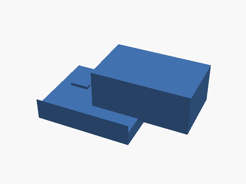
// Sharp GP2Y0A21YK0F Sensor Housing Model
// Units: millimeters (mm)

$fn = 64; // Increased detail for curved edges/cylinders

// --- Dimensions Definition (based on the drawing) ---
// Main Body Block dimensions (Approximate outer shell)
MAIN_W = 65;   // X-axis width
MAIN_H = 27;   // Z-axis height (Lens protrusion included)
MAIN_L = 40;   // Y-axis length

// Connecting Bar dimensions
BAR_THICKNESS = 10; // Z-thickness of the connecting bar
BAR_LENGTH = MAIN_L + 15; // Extending past main block end for mounting points

// Lens/Window Dimensions (Simplified representation)
LENS_DEPTH = 2.0; // Depth of the lens recess feature on top
RECEIVING_WINDOW_W = 12;
RECEIVING_WINDOW_H = 4;
TRANSMITTING_WINDOW_D = 8;
TRANSMITTING_WINDOW_W = 6;

// Mounting Hole Dimensions
HOLE_DIAMETER = 3.0;
HOLE_Z_POS = -5; // Positioned near the end of the connecting bar

module sensor_housing() {
    union() {
        // 1. Main Body Housing (The primary rectangular block)
        translate([0, 0, MAIN_H/2]) {
            cube([MAIN_W, MAIN_L, MAIN_H]);
        }

        // 2. Connecting Bar Extension (Bottom extension)
        // Note: This bar extends the overall length and provides mounting points.
        translate([-MAIN_W/2, -15, BAR_THICKNESS/2]) {
            cube([MAIN_W, BAR_LENGTH, BAR_THICKNESS]);
        }

        // 3. LENS WINDOWS (Features on the top face)
        // These are modeled as recessed areas or visible windows in the upper surface.

        // Receiving Lens Window (Left side, Rectangular)
        translate([-15, 0, MAIN_H - 0.1]) { // Z slightly below top surface for recess effect
            cube([RECEIVING_WINDOW_W, RECEIVING_WINDOW_H, LENS_DEPTH]);
        }

        // Transmitting Lens Window (Right side, Rectangular/Circular slot)
        translate([5, 0, MAIN_H - 0.1]) { // Z slightly below top surface for recess effect
            cube([TRANSMITTING_WINDOW_W, TRANSMITTING_WINDOW_D, LENS_DEPTH]);
        }

        // 4. MOUNTING HOLES (Subtracted from the Connecting Bar)
        difference() {
            // Start with a copy of the connecting bar volume to ensure accurate subtraction location
            translate([-MAIN_W/2, -15, BAR_THICKNESS]) {
                cube([MAIN_W, 0.1, BAR_THICKNESS]); // Thin slice where holes are placed
            }

            // Hole 1 (Left)
            translate([-(MAIN_W/2) + 4, -10, 0]) {
                cylinder(h=BAR_THICKNESS * 2, r=HOLE_DIAMETER/2);
            }

            // Hole 2 (Right)
            translate([(MAIN_W/2) - 4, -10, 0]) {
                cylinder(h=BAR_THICKNESS * 2, r=HOLE_DIAMETER/2);
            }
        }
    }
}

// Final render call
sensor_housing(); パラメータ (11) —
スライダを動かすと openscad-wasm で再レンダリング
prompt
添付画像は Sharp 製測距センサ GP2Y0A21YK0F のデータシートのページです。
OpenSCAD でモデリングしてください。

座標系: 単位 mm、本体の中心を原点とし、取付面(PWB / コネクタ側)を -Z に向ける。

完成したコード全体を ```openscad ... ``` のフェンスで囲んで出力してください。