pdf-page/gemma-4-e4b / tier-4-gp2y0a21yk
success tier 4
pdf-page (google/gemma-4-e4b)
render
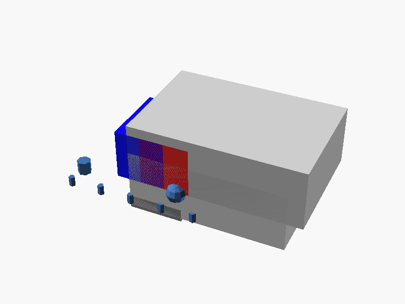
// Sharp GP2Y0A21YK0F Sensor Housing Model
// Units: mm
// Orientation: Origin (0, 0, 0) at center. Mounting face is in the -Z direction.

unit = mm;

// --- Global Parameters & Dimensions (Based on datasheet approximations) ---
// Overall length along X-axis
L_TOTAL = 47.5;
// Overall width along Y-axis
W_TOTAL = 29.5;
// Height of the main body/housing (Z-height)
H_BODY = 18;

// Connector dimensions (Bottom center feature)
CONN_L = 16.3;
CONN_W = 7.5;
CONN_H = 4; // Approximated height for mounting standoffs

// Emitter side (Left, X-min) and Detector side (Right, X-max) spacing
OFFSET_EMITTER = -20; // Approx start X coordinate of the emitter area
OFFSET_DETECTOR = 20; // Approx end X coordinate of the detector area


module main_housing() {
    // 1. Main Body Block (The encompassing structure)
    color([0.8, 0.8, 0.8])
    translate([0, 0, H_BODY/2])
    cube([L_TOTAL * 1.1, W_TOTAL + 5, H_BODY]); // Slightly oversized for fillet/tolerance

    // 2. Cut out the internal space (Creates the defined recess)
    difference() {
        // Start with the main body shape
        color("silver", 0.9) cube([L_TOTAL, W_TOTAL, H_BODY]);

        // Subtracting the connector mounting area/slot from the bottom center
        translate([0, 0, -1]) // Positioned slightly below the Z=0 plane
        cube([CONN_L, CONN_W, 2]);
    }
}


module emitter_assembly() {
    // Emitter Housing (Left Side)
    translate([OFFSET_EMITTER + L_TOTAL/2, 0, H_BODY/2])
    color("red", 0.8) // Representing the LED area
    cube([15, W_TOTAL * 0.7, H_BODY - 3]);

    // Emitter Details (Simulated component placement)
    translate([-15, 0, H_BODY/2 - 2])
    cylinder(h=4, r=2);
}


module detector_assembly() {
    // Detector Housing (Right Side)
    translate([OFFSET_DETECTOR - L_TOTAL/2, 0, H_BODY/2])
    color("blue", 0.8) // Representing the lens/detector area
    cube([15, W_TOTAL * 0.7, H_BODY - 3]);

    // Detector Lens (Simulated component placement)
    translate([15, 0, H_BODY/2])
    sphere(r=3);
}


module connector_block() {
    // The visible PCB Connector Block
    color("gray", 0.9)
    translate([0, 0, -CONN_H/2 + 1]) // Position slightly into the housing cavity
    cube([CONN_L, CONN_W, CONN_H]);

    // Simulated connection points (Pins)
    for (i = [-4, -2, 0, 2, 4]) {
        translate([i*5, 0, CONN_H/2-1.5])
        cylinder(h=3, r=1);
    }
}


// --- Assembly ---
module sensor_gp2y0a21yk0f() {
    // Main Housing (The primary chassis structure)
    main_housing();

    // Emitter side components
    emitter_assembly();

    // Detector side components
    detector_assembly();

    // Connector block attached to the bottom
    connector_block();
}

// Render the final model
sensor_gp2y0a21yk0f(); パラメータ (8) —
スライダを動かすと openscad-wasm で再レンダリング
prompt
添付画像は Sharp 製測距センサ GP2Y0A21YK0F のデータシートのページです。
OpenSCAD でモデリングしてください。

座標系: 単位 mm、本体の中心を原点とし、取付面(PWB / コネクタ側)を -Z に向ける。

完成したコード全体を ```openscad ... ``` のフェンスで囲んで出力してください。