pdf-page/gemini-3.8-flash / tier-4-gp2y0a21yk
success tier 4
pdf-page (gemini 3.8 flash)
render
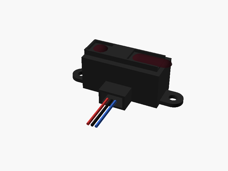
// Sharp GP2Y0A21YK0F 測距センサ 外形モデル
// 座標系: 本体中心が原点, +Z: 上方向(レンズ面), +Y: 前方, +X: 右方向
// 単位: mm

$fn = 40;

// --- 主要寸法パラメータ ---
// ケース本体ベース部
case_w = 29.5;      // X方向幅
case_l = 13.0;      // Y方向長さ (本体部)
case_h = 13.5;      // Z方向厚み (背面から前面まで)

// レンズ枠突起部 (前面上部)
lens_frame_w = 27.95; // 7.5 + 4.15 + 16.3
lens_frame_l = 8.4;
lens_frame_h = 2.0;   // 前面からの突出量

// レンズ位置 (左端 X = -case_w/2 = -14.75 からの距離)
emitter_cx = -14.75 + 4.5;       // -10.25 mm
detector_cx = emitter_cx + 20.0; // +9.75 mm
lens_cy = 0;                     // Y方向中心

// 取付耳 (フランジ)
mount_pitch = 37.0; // 穴中心間ピッチ
mount_hole_d = 3.2; // 取付穴径
mount_r = 3.75;     // 外形半径
mount_t = 1.5;      // 板厚

// コネクタ部 (-Y方向)
conn_w = 10.1;
conn_l = 5.9;       // 全高18.9 - 13.0
conn_h = 6.0;

module gp2y0a21yk0f() {
    // 1. ケース本体 (黒色樹脂)
    color([0.15, 0.15, 0.15]) {
        difference() {
            union() {
                // メイン直方体ベース
                cube([case_w, case_l, case_h], center = true);

                // レンズ枠突出部 (Z上面)
                translate([emitter_cx - 4.5 + lens_frame_w/2, 0, case_h/2 + lens_frame_h/2])
                    cube([lens_frame_w, lens_frame_l, lens_frame_h], center = true);

                // 取付耳 (背面側 Z = -case_h/2 に配置)
                for (side = [-1, 1]) {
                    hull() {
                        translate([side * (case_w/2 - 2), 0, -case_h/2 + mount_t/2])
                            cube([4, mount_r * 2, mount_t], center = true);
                        translate([side * mount_pitch/2, 0, -case_h/2 + mount_t/2])
                            cylinder(r = mount_r, h = mount_t, center = true);
                    }
                }

                // コネクタハウジング部 (-Y側突出)
                translate([0, -case_l/2 - conn_l/2, -case_h/2 + conn_h/2])
                    cube([conn_w, conn_l, conn_h], center = true);
            }

            // 取付穴 (φ3.2 mm x 2)
            for (side = [-1, 1]) {
                translate([side * mount_pitch/2, 0, -case_h/2])
                    cylinder(d = mount_hole_d, h = mount_t * 4, center = true);
            }

            // レンズ開口部の凹み
            // 発光側開口 (7.5 x 7.2)
            translate([emitter_cx, lens_cy, case_h/2 + lens_frame_h - 0.5])
                cube([7.5, 7.2, 1.2], center = true);

            // 受光側開口 (16.3 x 7.2)
            translate([detector_cx, lens_cy, case_h/2 + lens_frame_h - 0.5])
                cube([16.3, 7.2, 1.2], center = true);

            // コネクタ嵌合口の切欠き
            translate([0, -case_l/2 - conn_l/2 - 0.5, -case_h/2 + conn_h/2])
                cube([conn_w - 2.0, conn_l, conn_h - 1.5], center = true);
        }
    }

    // 2. 光学レンズ部 (可視光カットのアクリル樹脂: 半透明暗赤色/黒)
    color([0.2, 0.05, 0.08, 0.85]) {
        // 発光側レンズ (平凸円形レンズ)
        translate([emitter_cx, lens_cy, case_h/2 + lens_frame_h - 0.5]) {
            intersection() {
                translate([0, 0, -2.5])
                    sphere(r = 3.5);
                translate([0, 0, 0.5])
                    cube([7.0, 7.0, 1.5], center = true);
            }
        }

        // 受光側レンズ (横長凸面レンズ)
        translate([detector_cx, lens_cy, case_h/2 + lens_frame_h - 0.5]) {
            intersection() {
                hull() {
                    translate([-4.5, 0, -2.5]) sphere(r = 3.5);
                    translate([ 4.5, 0, -2.5]) sphere(r = 3.5);
                }
                translate([0, 0, 0.5])
                    cube([15.5, 7.0, 1.5], center = true);
            }
        }
    }

    // 3. ケーブル / コネクタピン簡易表現 (3本線)
    wire_colors = [[0.8, 0.2, 0.2], [0.1, 0.1, 0.1], [0.2, 0.4, 0.8]]; // Vcc(赤), GND(黒), Vo(青)
    for (i = [-1:1]) {
        color(wire_colors[i + 1]) {
            translate([i * 1.5, -case_l/2 - conn_l, -case_h/2 + conn_h/2]) {
                rotate([90, 0, 0])
                    cylinder(r = 0.5, h = 15, center = false);
            }
        }
    }
}

// モデル呼出し
gp2y0a21yk0f(); パラメータ (14) —
スライダを動かすと openscad-wasm で再レンダリング
prompt
添付画像は Sharp 製測距センサ GP2Y0A21YK0F のデータシートのページです。
OpenSCAD でモデリングしてください。

座標系: 単位 mm、本体の中心を原点とし、取付面(PWB / コネクタ側)を -Z に向ける。

完成したコード全体を ```openscad ... ``` のフェンスで囲んで出力してください。