pdf-page/gemini-3.5-flash-lite / tier-4-gp2y0a21yk
success tier 4
pdf-page (gemini 3.5 flash-lite)
render
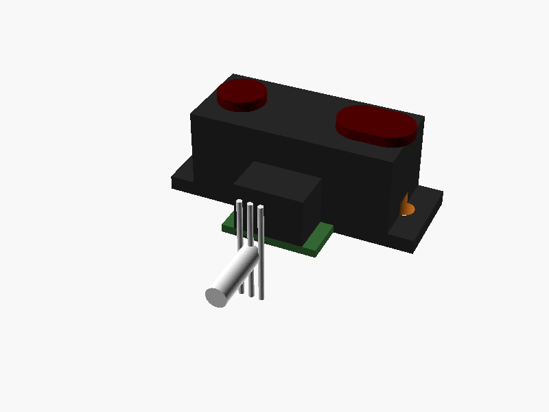
loading STL…
// Sharp GP2Y0A21YK0F Distance Measuring Sensor
// Units: mm
// Coordinate system:
//   X: width (left-right)
//   Y: depth (front-back, lens facing +Y)
//   Z: height (bottom-top, base at bottom, lenses at top)
// Origin (0,0,0) is centered at the middle of the main body (X and Y),
// with Z=0 at the bottom mounting flange level.

$fn = 64;

module gp2y0a21yk0f() {
    // Colors
    c_case = [0.15, 0.15, 0.15, 1];   // Dark gray ABS case
    c_lens = [0.3, 0.0, 0.0, 1];     // Dark red/blackish IR acrylic
    c_pwb  = [0.2, 0.4, 0.2, 1];     // Green PWB
    c_pin  = [0.8, 0.7, 0.2, 1];     // Gold pins
    c_wire = [0.9, 0.9, 0.9, 1];     // Cable

    translate([0, 0, 0]) {

        // 1. Main Lens Case (Upper block)
        // Width: 29.5 (main body section), total width with mounting ears is 37
        // Depth: 13
        // Height: 13.5 (from mounting flange to top of case)
        color(c_case)
        translate([-29.5/2, -13/2, 2.15])
            cube([29.5, 13, 13.5 - 2.15]);

        // 2. Mounting Flange / Wings (Tabs on left and right)
        // Overall width: 37
        // Thickness of flange: 2.15 (or 2.15 to 1.5, let's use 2.15)
        // Depth of flange: 13 at center, but ends are rounded with R3.75
        color(c_case) {
            // Main rectangular strip of the flange
            translate([-37/2, -13/2, 0])
                cube([37, 13, 2.15]);

            // Left rounded end
            translate([-37/2 + 3.75, 0, 0])
                cylinder(r=3.75, h=2.15);

            // Right rounded end
            translate([37/2 - 3.75, 0, 0])
                cylinder(r=3.75, h=2.15);
        }

        // Subtract mounting holes (dia 3.2, centers at ±14.75 from center)
        // Center-to-center distance of holes is 29.5 (implied by symmetry and 37 total - margins)
        // Actually, looking at the drawing: total width 37, hole centers are at the centers of the R3.75 radii.
        // R3.75 means radius is 3.75, so hole is at 37/2 - 3.75 = 18.5 - 3.75 = 14.75 from center.
        // Let's verify: 14.75 * 2 = 29.5. Exactly matches!

        // We can subtract the holes using difference() for the whole assembly if needed,
        // or just model cleanly. Let's make a module or use difference for the base.

        // 3. Lenses on top (+Z direction)
        // Lens protrusion height: total height is 13.5 + lens protrusion (~1.5mm) -> let's make lens block extend to Z = 15
        // Light emitter (Left, center at X = -10 relative to center, since 20mm spacing, so ±10)
        // Wait, drawing shows *20±0.1 distance between lens centers.
        // So left lens at X = -10, right lens at X = +10.

        // Emitter lens (circular/square protrusion on top)
        color(c_lens)
        translate([-10, 0, 13.5])
            cylinder(r=3.5, h=1.5);

        // Detector lens (PSD) - rectangular with rounded corners or pill shape
        color(c_lens)
        translate([10, 0, 13.5])
            // 7.2 x 8.4 area roughly, let's use a rounded box or scaled cylinder
            hull() {
                translate([-2, 0, 0]) cylinder(r=3.5, h=1.5);
                translate([ 2, 0, 0]) cylinder(r=3.5, h=1.5);
            }

        // 4. PWB and Connector section at the bottom/back (-Y side)
        // PWB protrudes backwards (-Y) by 6.3 from front face?
        // Let's check dimensions:
        // From front face (-13/2 = -6.5) to back of PWB is 6.3.
        // So PWB extends from Y = -6.5 to Y = -6.3 + ... wait.
        // "6.3" is dimension from front lens case face to back of PWB?
        // Let's re-read: Dimension 6.3 is from front flat face of lens case to the back edge of the connector/PWB.
        // Lens case depth = 13 (from -6.5 to +6.5 in Y).
        // Front face is at Y = +6.5. Back face of lens case is at Y = -6.5.
        // PWB extends backwards to Y = -6.5 - 6.3 = -12.8? Or total depth is 6.3 behind front?
        // Looking at the right-side view:
        // Front of lens case to back of connector is 6.3.
        // Lens case thickness is 13? No, 13 is height or depth?
        // Side view shows: width/depth of body is 13 (vertical in top view, horizontal in side view).
        // Let's trace side view:
        // Lens case depth = 13.
        // From front of lens case to back of Pakage/Connector = 6.3? No, 6.3 is distance from front to back of connector?
        // Ah, "2" is lens case front protrusion, total depth 6.3 is from front of lens to back of PWB.
        // Let's place PWB and connector accurately based on drawing:
        // PWB extends at the bottom rear (-Y). Width of connector section = 10.1.

        // Connector housing (black plastic box at bottom rear)
        color(c_case)
        translate([-10.1/2, -12.8, 0])
            cube([10.1, 6.3, 8.4]); // 8.4 height of connector area from side view

        // Pins inside connector (3 pins)
        for (i = [-1, 0, 1]) {
            color(c_pin)
            translate([i * 2.0, -10, 4])
                cube([0.6, 0.6, 5], center=true);
        }

        // PWB base plate extending slightly
        color(c_pwb)
        translate([-14/2, -12.8, 0])
            cube([14, 6.3, 1.2]);

        // 5. Cable (JST PHR-3 style bundled wires exiting the connector downwards/backwards)
        color(c_wire) {
            translate([0, -12.8 - 5, 2])
            rotate([90, 0, 0])
                cylinder(r=1.5, h=10);

            // Individual wires trailing down
            translate([-1.5, -18, -5]) cylinder(r=0.4, h=15);
            translate([ 0.0, -18, -5]) cylinder(r=0.4, h=15);
            translate([ 1.5, -18, -5]) cylinder(r=0.4, h=15);
        }
    }
}

// Render the sensor with mounting holes subtracted
difference() {
    gp2y0a21yk0f();

    // Left mounting hole
    translate([-14.75, 0, -1])
        cylinder(r=3.2/2, h=5);

    // Right mounting hole
    translate([14.75, 0, -1])
        cylinder(r=3.2/2, h=5);
}prompt
添付画像は Sharp 製測距センサ GP2Y0A21YK0F のデータシートのページです。
OpenSCAD でモデリングしてください。

座標系: 単位 mm、本体の中心を原点とし、取付面(PWB / コネクタ側)を -Z に向ける。

完成したコード全体を ```openscad ... ``` のフェンスで囲んで出力してください。