pdf-page/gemini-3.1-pro / tier-4-gp2y0a21yk
success tier 4
pdf-page (gemini 3.1 pro)
render
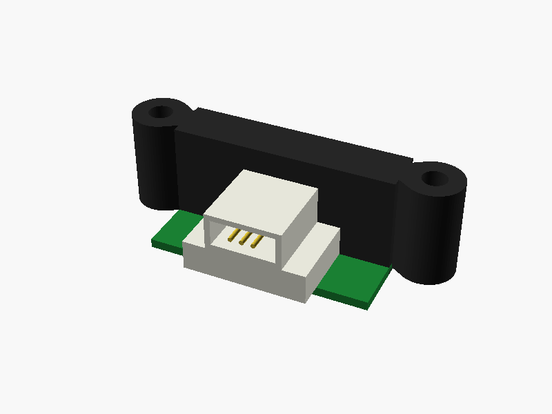
loading STL…
/*
  Sharp GP2Y0A21YK0F Distance Sensor
  Units: mm
  Coordinate System:
    Origin (0,0,0) is at the center of the main body block.
    Mounting surface (PWB / Connector side) points towards -Z.
    Lens faces +Y direction.
*/

$fn = 64;

module GP2Y0A21YK0F() {
    // --- Color definitions ---
    color_body = [0.15, 0.15, 0.15]; // Black/Dark Gray for casing
    color_lens = [0.05, 0.05, 0.10]; // Dark blue-ish for lenses
    color_pcb  = [0.10, 0.50, 0.20]; // Green for PWB
    color_conn = [0.90, 0.90, 0.85]; // Off-white for connector housing
    color_pin  = [0.80, 0.70, 0.20]; // Gold/Brass for pins

    // 1. Main Body Box
    // Width: 29.5 (X: -14.75 to 14.75)
    // Depth: 6.3  (Y: -3.15 to 3.15)
    // Height: 13.5 (Z: -6.75 to 6.75)
    color(color_body)
    cube([29.5, 6.3, 13.5], center=true);

    // 2. Mounting Flanges
    // Distance between hole centers: 37 (X = +/- 18.5)
    // Hole diameter: 3.2 (r = 1.6)
    // Flange outer radius: R3.75
    // Height: 13 (Z: -6.25 to 6.75, offset by 0.25mm to align top)
    // Depth: estimated 4mm thick (Y: -2.0 to 2.0)
    color(color_body)
    for (i = [-1, 1]) {
        difference() {
            hull() {
                // Outer cylindrical part of flange
                translate([i * 18.5, 0, 0.25])
                cylinder(h=13, r=3.75, center=true);

                // Connection to the main body box
                translate([i * 14.75, 0, 0.25])
                cube([0.1, 4, 13], center=true);
            }
            // Mounting holes
            translate([i * 18.5, 0, 0.25])
            cylinder(h=14, r=1.6, center=true);
        }
    }

    // 3. Lens Case (Front block)
    // Spans from Left lens center(-10.25) to Right lens center(9.75)
    // Protrudes 2mm out from front face (Y: 3.15 to 5.15)
    // Height: 8.4 (r = 4.2 for rounded ends)
    color(color_body)
    translate([0, 3.15 + 1, 0])
    rotate([90, 0, 0])
    hull() {
        translate([-10.25, 0, 0]) cylinder(h=2, r=4.2, center=true);
        translate([  9.75, 0, 0]) cylinder(h=2, r=4.2, center=true);
    }

    // 4. Lenses
    // Left (Emitter), Right (Detector)
    // Diameter approx 7.2 (r = 3.6), modeled as flattened spheres
    color(color_lens) {
        // Left lens (4.5mm from left edge of 29.5mm body -> X = -10.25)
        translate([-10.25, 4.3, 0])
        scale([1, 0.25, 1])
        sphere(r=3.6);

        // Right lens (20mm from left lens -> X = 9.75)
        translate([9.75, 4.3, 0])
        scale([1, 0.25, 1])
        sphere(r=3.6);
    }

    // 5. PWB (Printed Wiring Board)
    // Total depth dimension is (18.9). Front is at Y=5.15, Back connector is at Y=-13.75.
    // PWB protrudes backwards by (3.3) shorter than the connector end -> Y = -10.45.
    // Length = 3.15 to -10.45 (L = 13.6)
    // Thickness: 1.2 (Z: -6.75 to -5.55)
    color(color_pcb)
    translate([0, -3.65, -6.15])
    cube([29.5, 13.6, 1.2], center=true);

    // 6. Connector (JCTC / 1.5mm pitch 3-pin style)
    // Base block: W=16.3, L=10.6 (Y: -3.15 to -13.75)
    // Height: 4 (Z: -5.55 to -1.55)
    color(color_conn) {
        translate([0, -8.45, -3.55])
        cube([16.3, 10.6, 4], center=true);

        // Top block: W=10.1, L=10.6, H=5 (Z: -1.55 to 3.45)
        difference() {
            translate([0, -8.45, 0.95])
            cube([10.1, 10.6, 5], center=true);

            // Opening for pins (Facing backwards: -Y direction)
            translate([0, -11.25, 0.95])
            cube([8.5, 5.1, 3.5], center=true);
        }
    }

    // 7. Connector Pins (Vo, GND, Vcc)
    // Approximated at 1.5mm pitch
    color(color_pin)
    for(i = [-1, 0, 1]) {
        translate([i * 1.5, -12.5, 0.95])
        rotate([90, 0, 0])
        cylinder(h=3, r=0.3, center=true);
    }
}

// Render the module
GP2Y0A21YK0F();prompt
添付画像は Sharp 製測距センサ GP2Y0A21YK0F のデータシートのページです。
OpenSCAD でモデリングしてください。

座標系: 単位 mm、本体の中心を原点とし、取付面(PWB / コネクタ側)を -Z に向ける。

完成したコード全体を ```openscad ... ``` のフェンスで囲んで出力してください。